Joystick steering on power machine with filtered steering input

a technology of power machines and joysticks, which is applied in the direction of mechanical control devices, manual control with single control members, instruments, etc., can solve the problems of unwanted movement of joysticks and unrepeated control input to the power machin

Inactive Publication Date: 2005-02-15
CLARK EQUIP CO INC
View PDF44 Cites 25 Cited by
  • Summary
  • Abstract
  • Description
  • Claims
  • Application Information

AI Technical Summary

Problems solved by technology

It has been found that, under certain operating conditions, relative movement of the user and the power machine can cause unwanted movement of the joysticks.
For example, if the power machine is moving over rough terrain, the user may inadvertently move the joystick, thereby causing undesired control input to the power machine.

Method used


Image

  • Joystick steering on power machine with filtered steering input
  • Joystick steering on power machine with filtered steering input
  • Joystick steering on power machine with filtered steering input

Examples


Embodiment Construction

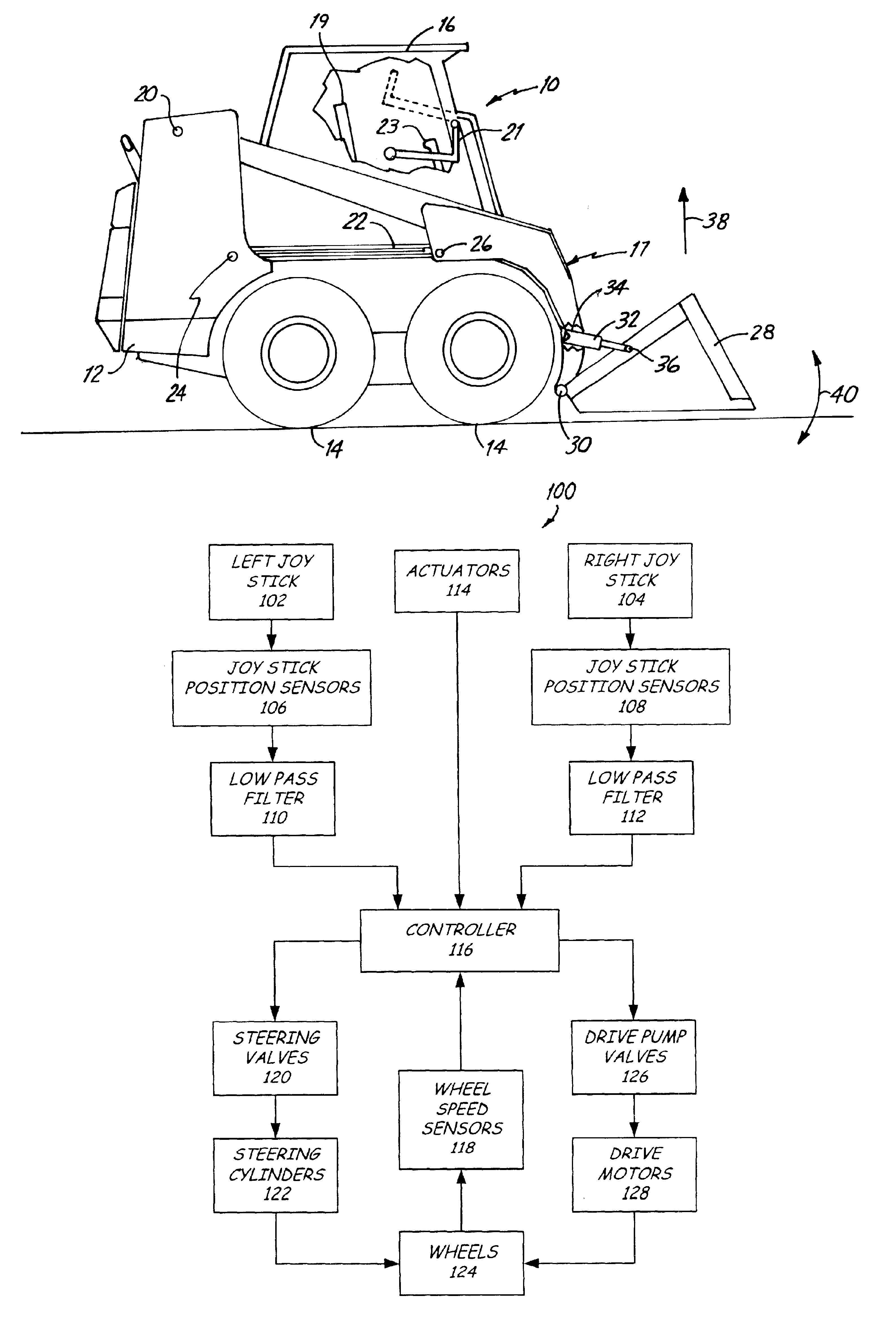
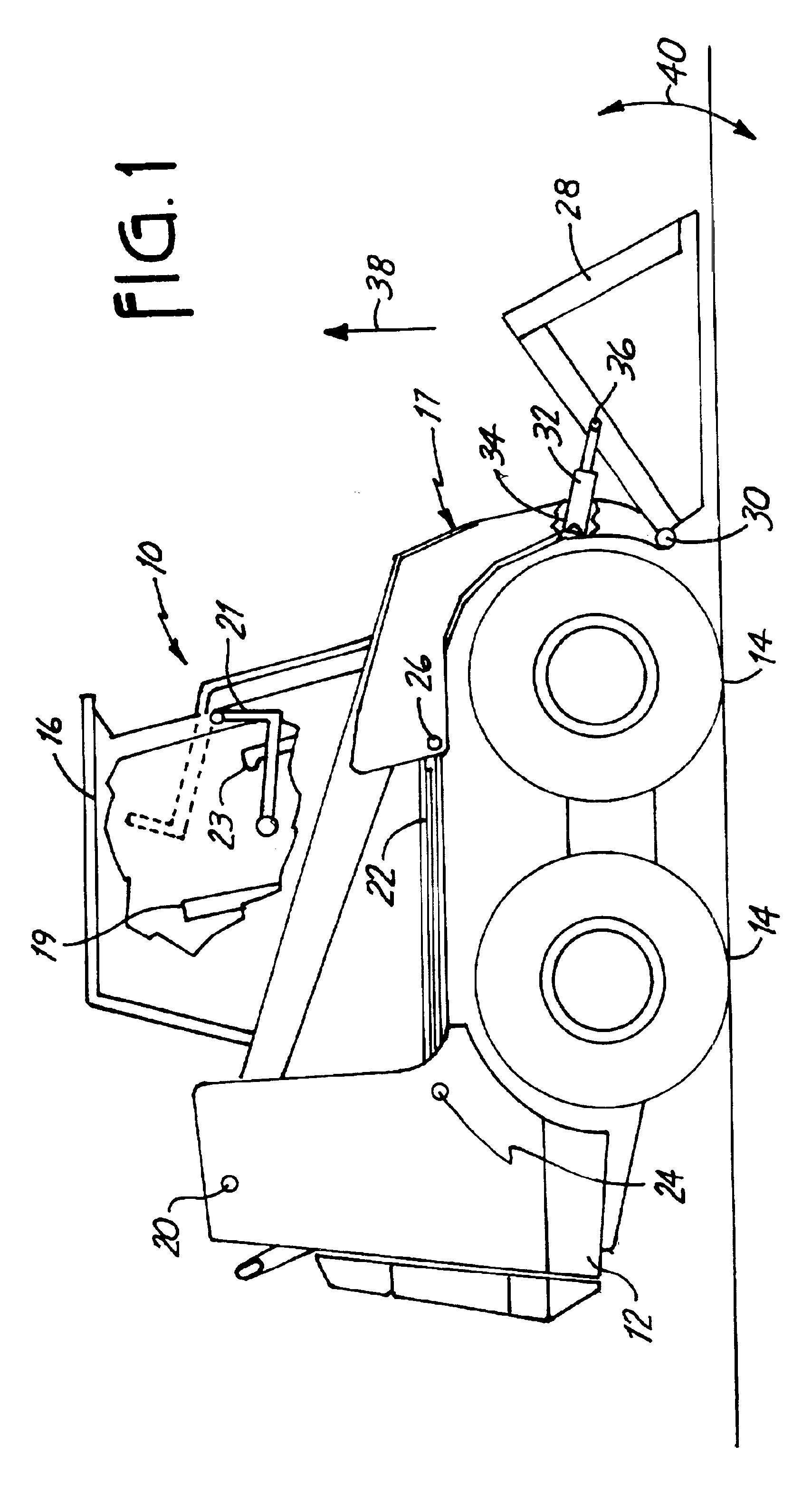
FIG. 1 is a side elevational view of one embodiment of a loader 10 according to the present invention. Loader 10 includes a frame 12 supported by wheels 14. Frame 12 also supports a cab 16 which defines an operator compartment and which substantially encloses a seat 19 on which an operator sits to control skid steer loader 10. A seat bar 21 is optionally pivotally coupled to a (e.g. front or rear) portion of cab 16. When the operator occupies seat 19, the operator then pivots seat bar 21 from the raised position (shown in phantom in FIG. 1) to the lowered position shown in FIG. 1.

A pair of steering joysticks 23 (only one of which is shown in FIG. 1) are mounted within cab 16. In one embodiment, one of joysticks 23 is manipulated by the operator to control forward and rearward movement of loader 10, and in order to steer loader 10, while the other joystick 23 is manipulated to control functions of the loader and in order to steer loader. One embodiment of joystick 23 is illustrated i...


PUM


Abstract

A user input device in accordance with one features of the present invention includes one or more joysticks, movable by a user in an operator compartment of a power machine. The joysticks control direction of movement of the power machine, as well as travel speed.

Description

BACKGROUND OF THE INVENTIONThe present invention generally relates to user input devices for power machines. In particular, the present invention relates to a filtered joystick input to a power machine.Power machines, such as loaders, typically have a number of power actuators. Such actuators can include, for example, drive actuators which provide traction power to the wheels or tracks of the machine. The actuators can also include those associated with manipulating a primary working tool, such as a bucket. In that case, the actuators include lift and tilt actuators. Of course, a wide variety of other actuators can also be used on such power machines. Examples of such actuators include auxiliary actuators, hand-held or remote tool actuators or other actuators associated with the operation of the power machine itself, or a tool coupled to the power machine.The various actuators on such power machines have conventionally been controlled by mechanical linkages. For example, when the ac...

Claims


Application Information

Patent Timeline
Patent Type & Authority Patents(United States)
IPC IPC(8): E02F9/22E02F3/34E02F3/28G05G9/047G05G9/00G05G25/00G05G25/02
CPCE02F3/34E02F9/225G05G25/02G05G9/047Y10T74/20201G05G2009/04774
Inventor BRANDT, KENNETH A.ROSSOW, SCOTT R.
Owner CLARK EQUIP CO INC
Why Eureka
Try Eureka