

Undermount drawer slide
a drawer slide and undermount technology, applied in drawers, furniture parts, domestic applications, etc., can solve the problems of affecting the cabinet or other supporting structure is not adapted to bear loads, and the design of the undermount drawer slide is complicated
- Summary
- Abstract
- Description
- Claims
- Application Information
AI Technical Summary
Benefits of technology
Problems solved by technology
Method used
Image

Examples
Embodiment Construction
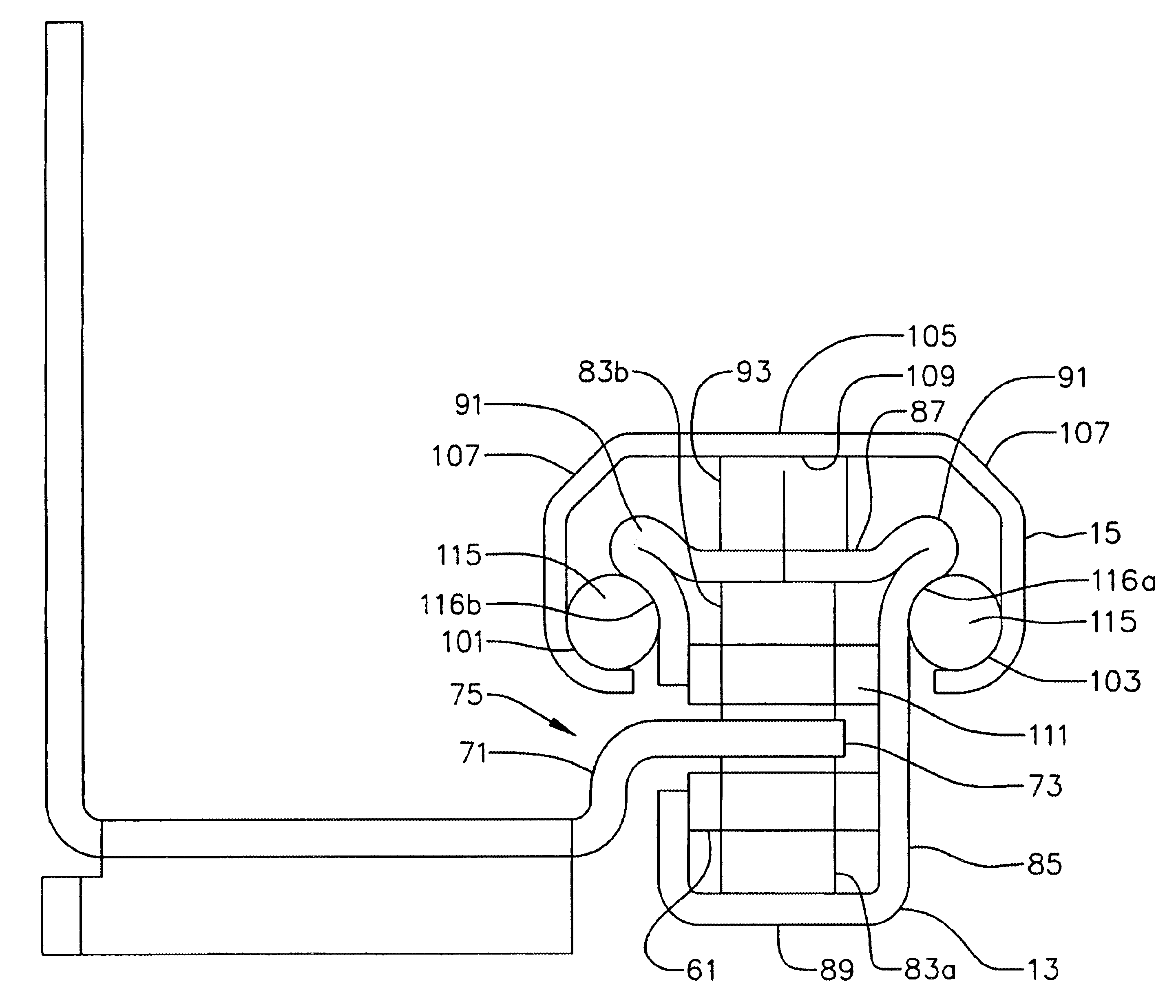
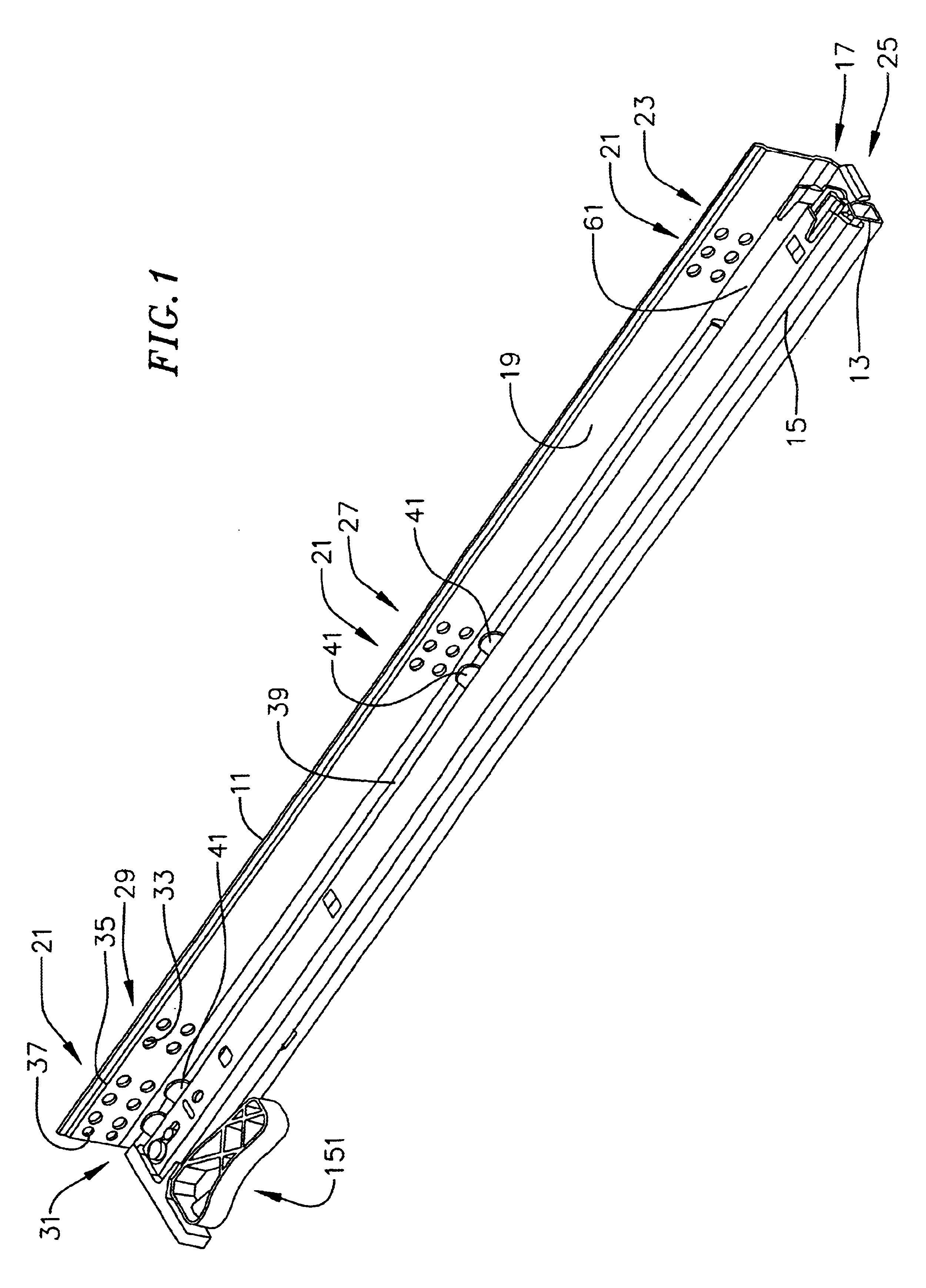
FIG. 1 illustrates a perspective view of an undermount drawer slide in accordance with aspects of the invention. The undermount drawer slide of FIG. 1 includes three rails. The rails include a cabinet rail 11 adapted for mounting to a side of a cabinet, an intermediate rail 13 coupled to the cabinet rail, and a shelf rail 15 coupled to the intermediate rail. The shelf rail is adapted for connection with a drawer or shelf or the like.
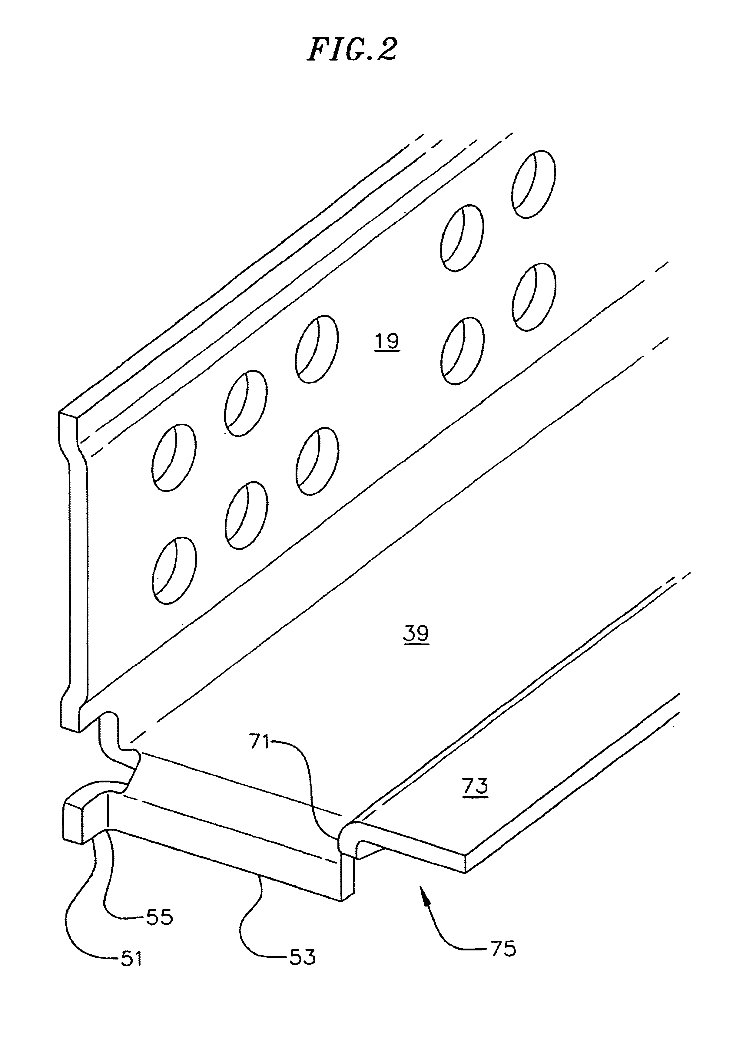
The cabinet rail includes an L-shaped bracket 17 extending away from the intermediate rail, and an offset flange 75 (shown in FIG. 3) extending from an edge of the L-shaped bracket. The offset flange couples the cabinet rail to the intermediate rail, and the L-bracket is used to couple the cabinet rail to a side of a cabinet.
A first part 19 of the L-shaped bracket, distal from the intermediate rail, is used for coupling to a side of the cabinet. In the embodiment of FIG. 1, the first part of the L-shaped bracket includes patterned mounting holes 21. The ...
PUM
 Abstract
Description
Claims
Application Information