Shoulder or hip prosthesis and process for fitting same

a technology for hips and shoulders, applied in the field of shoulder or hip prosthesis, can solve the problems of unstable prosthesis and very invasive glenoid component of such a surfa

Inactive Publication Date: 2005-07-28
TORNIER SA SAINT ISMIER
View PDF99 Cites 111 Cited by
  • Summary
  • Abstract
  • Description
  • Claims
  • Application Information

AI Technical Summary

Benefits of technology

[0006] Thanks to the invention, the retaining member contributes to the stability of the prosthesis, while the non-circular nature of the passage in which the neck is displaced makes it possible to envisage movements of abduction of great amplitude.

Problems solved by technology

The glenoid component of such a surface is very invasive and a subacromial conflict of the humeral component may occur at the end of the movement of abduction.
Such a prosthesis is unstable insofar as no means is provided for avoiding that the two bones cooperating with the intermediate element, move apart from each other.

Method used


Image

  • Shoulder or hip prosthesis and process for fitting same
  • Shoulder or hip prosthesis and process for fitting same
  • Shoulder or hip prosthesis and process for fitting same

Examples


first embodiment

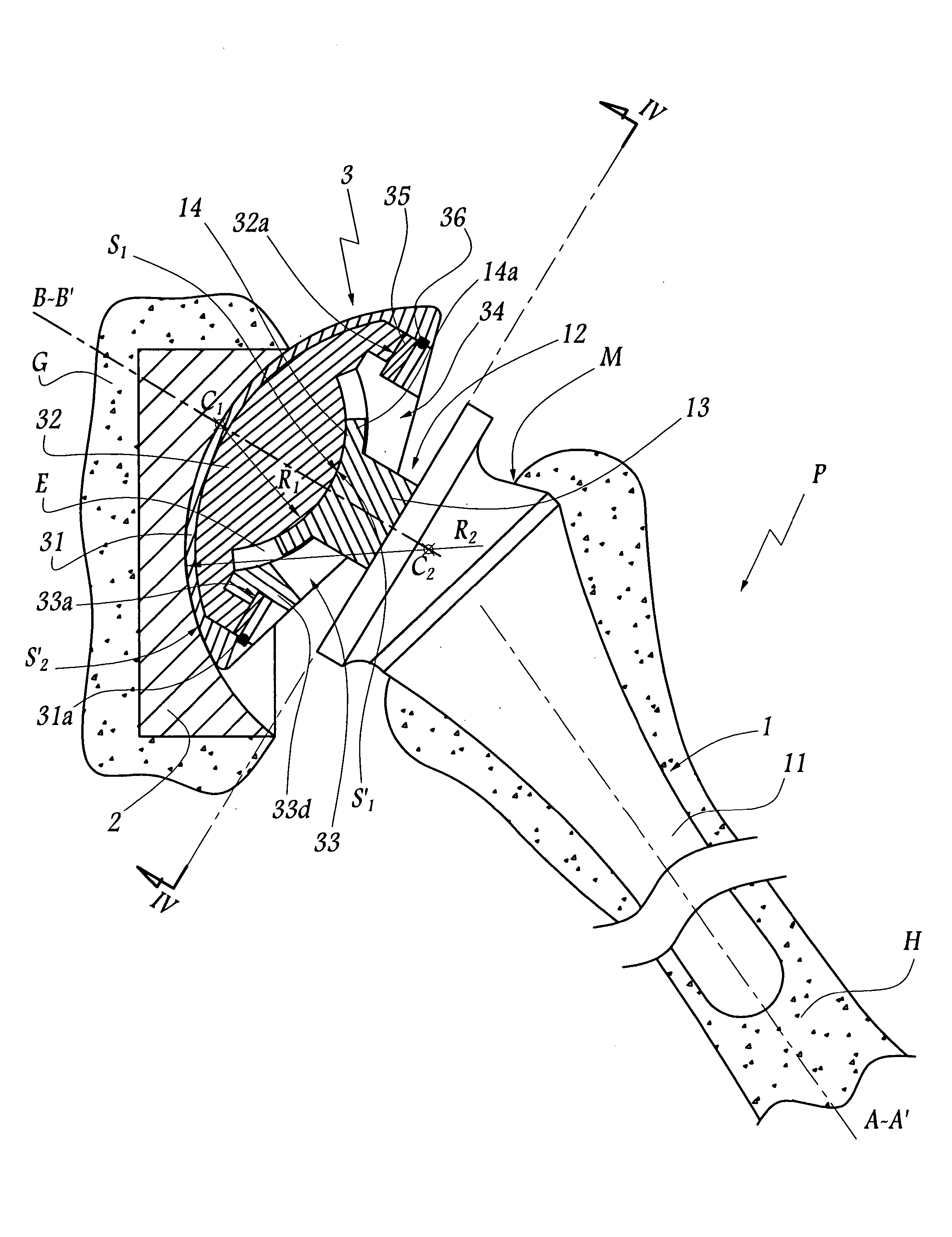
[0058] As in the first embodiment, the plate 114 is retained in abutment on the surface S′1 during the whole movement of abduction, including in central position corresponding to that of FIG. 1.

[0059] In the third embodiment of the invention shown in FIGS. 9 and 10, elements similar to those of the first embodiment bear identical references increased by 200. This embodiment concerns a shoulder prosthesis whose intermediate component 203 comprises a cup 231 and a ring 233 whose central opening 234 is of substantially elliptical shape, with its longitudinal axis X234-X′234 substantially parallel to the sagittal plane.

[0060] The sub-assembly 212 of the humeral component 201, which forms a surface of articulation S1 adapted to cooperate with the surface of articular S′1 defined by the insert 232 of the component 203, is more particularly visible in FIG. 9. Its plate 214 is of substantially elliptical shape, its neck 313 being circular; The neck 213 is adapted to be immobilized on a fla...

second embodiment

[0063] The neck 213 and the flange 215 may be connected before or after the plate 214 is applied against the surface S′1. This also applies to the

[0064] According to a variant of the invention (not shown), the flange 215 and the part 211 intended to be anchored in the medullary cavity are in one piece. According to another variant, the neck 213 is introduced directly in a housing formed by the part 211.

[0065] In the fourth embodiment of the invention shown in FIG. 11, elements similar to those of the first embodiment bear identical references. The medullary stem 11 defines a truncated housing 11a centred on an axis X11 and bordered by a substantially annular bearing surface 11b. The plate 14 and the neck 13 are in one piece with the flange 15 and with a stud 17 intended to be introduced in the housing 11a and immobilized therein by cooperation of shapes. The assembly formed by elements 13, 14, 15 and 17 is visible in plan view in FIG. 12. The outer surface of the stud 17 is truncat...


PUM


Abstract

This prosthesis comprises a humeral or femoral component and an intermediate component. The concave surface of articulation of the humeral or femoral component is formed by a plate connected by a neck to a part of this component adapted to be anchored in the humeral or femoral medullary cavity. The intermediate component is provided with a member for retaining the humeral or femoral component in a position where the plate is in abutment against the first convex surface of the intermediate component. The retaining member defines a non-circular passage in which the neck is adapted to be displaced as a function of the movements of the humeral or femoral component with respect to the other components of the prosthesis. The retaining member defines with the first convex surface of articulation of the intermediate component a volume for receiving a part of the plate projecting radially with respect to the neck.

Description

FIELD OF THE INVENTION [0001] The present invention relates to a complete or partial shoulder or hip prosthesis making it possible to reproduce, with an improved degree of precision, the characteristics of the natural joints. The invention also relates to a process for assembling such a prosthesis. BACKGROUND OF THE INVENTION [0002] In the domain of shoulder prostheses, it is known, for example from EP-A-0 299 889, to create a convex articular surface on a glenoid component, while a concave articular surface, of corresponding shape, is formed on a humeral component. The glenoid component of such a surface is very invasive and a subacromial conflict of the humeral component may occur at the end of the movement of abduction. [0003] Furthermore, U.S. Pat. No. 4,846,840 discloses providing, on an intermediate element of a prosthesis, two substantially concentric convex surfaces with a view to their articulation on concave surfaces of corresponding shape, respectively provided on two bon...

Claims


Application Information

Patent Timeline
Patent Type & Authority Applications(United States)
IPC IPC(8): A61F2/00A61F2/30A61F2/32A61F2/34A61F2/36A61F2/40A61F2/46A61F2/48
CPCA61F2/32A61F2310/00179A61F2/367A61F2/40A61F2/4059A61F2/4081A61F2/4637A61F2002/30112A61F2002/30125A61F2002/30131A61F2002/30153A61F2002/30324A61F2002/30332A61F2002/30354A61F2002/30377A61F2002/3038A61F2002/30387A61F2002/3039A61F2002/30497A61F2002/30514A61F2002/30543A61F2002/30574A61F2002/30604A61F2002/30642A61F2002/30649A61F2002/30662A61F2002/3625A61F2002/3631A61F2002/3652A61F2002/4029A61F2002/4044A61F2002/48A61F2220/0025A61F2220/0033A61F2230/0004A61F2230/0008A61F2230/0013A61F2230/0019A61F2250/0036A61F2/34A61F2002/30367A61F2002/30331A61F2002/30495A61F2002/3054A61F2/48
Inventor TORNIER, ALAIN
Owner TORNIER SA SAINT ISMIER
Why Eureka
Try Eureka