Device for monitoring cardiac compression, resuscitation mask and method of applying cardiac compression

a technology of cardiac compression and resuscitation mask, which is applied in the direction of respiratory mask, artificial respiration, visible signalling system, etc., can solve the problems of most reliable people performing below their best, cardiac and respiratory failure instances, and long tim

Inactive Publication Date: 2005-02-22
MEDTEQ HLDG
View PDF17 Cites 16 Cited by
  • Summary
  • Abstract
  • Description
  • Claims
  • Application Information

AI Technical Summary

Problems solved by technology

Most of these instances of cardiac and respiratory failure occur outside of the presence of trained medical personnel.
While many members of the public may learn CPR at one time or another it may be a long time since they have applied CPR when they are actually confronted by a crisis which requires them to perform it.
Furthermore, even if a person has trained in CPR relatively recently, the pressure of a crisis situation can cause even the most reliable of persons to perform below their best.
It is particularly difficult for a person who has learnt how to apply cardiac compressions some time ago to know whether they are applying sufficient force to the sternum of the patient and thus the heart.
If too little pressure is applied, there will be insufficient compression of the heart to have the desired effect, whereas too much pressure can lead to broken ribs or a broken sternum and hence impaired breathing.
Furthermore, if the patient's ribs are broken when CPR is applied this causes additional complications when the patient is taken to hospital.
Damage to the patient's rib cage may be caused not only by excessive application of force but also by inaccurate application of force where force is not applied to the sternum but rather to the surrounding rib area.
Such masks are relatively large and cumbersome to use and require two hands to be held in place properly.
This mask with portions which press against the open ends of the nostril passages has a disadvantage in that where the patient's nostrils are subject to flaring, as is genetically inherent among some racial groups, the mask will not seal the nostrils effectively and therefore fluid will be able to pass undesirably through the nostrils.

Method used


Image

  • Device for monitoring cardiac compression, resuscitation mask and method of applying cardiac compression
  • Device for monitoring cardiac compression, resuscitation mask and method of applying cardiac compression
  • Device for monitoring cardiac compression, resuscitation mask and method of applying cardiac compression

Examples


Embodiment Construction

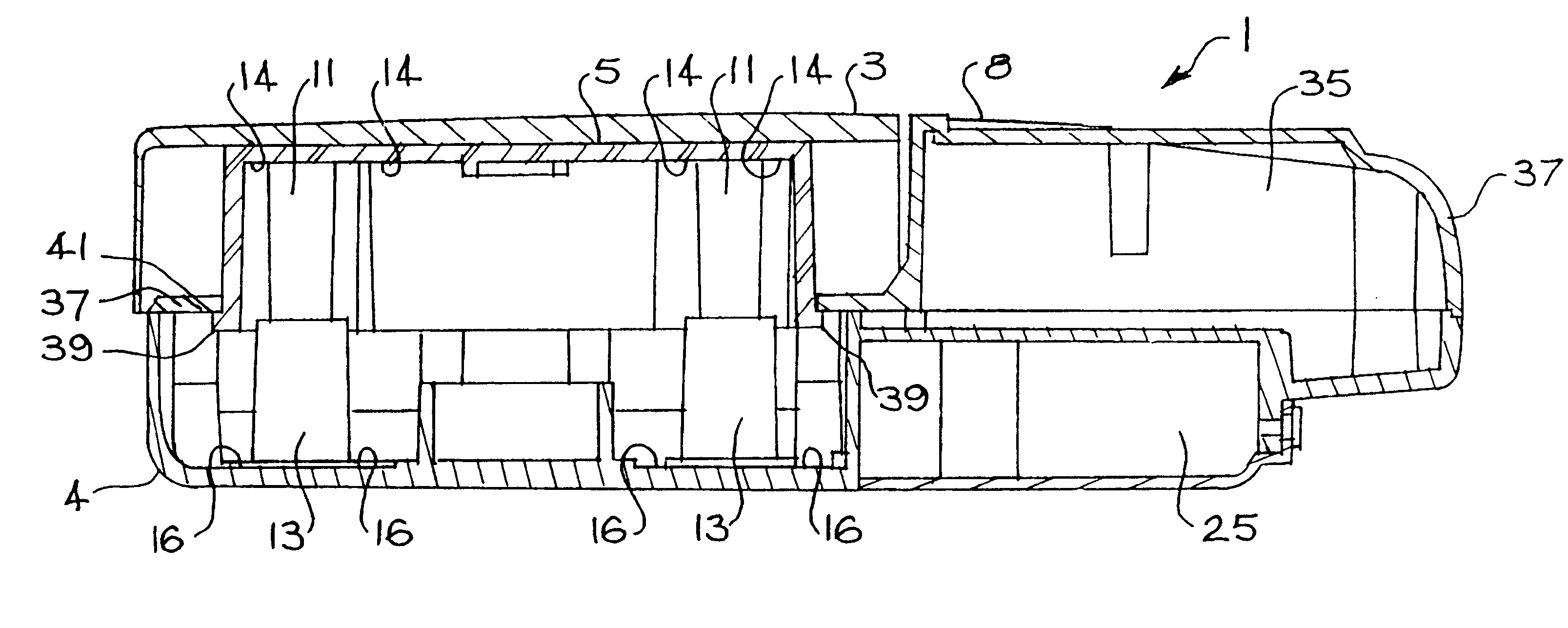
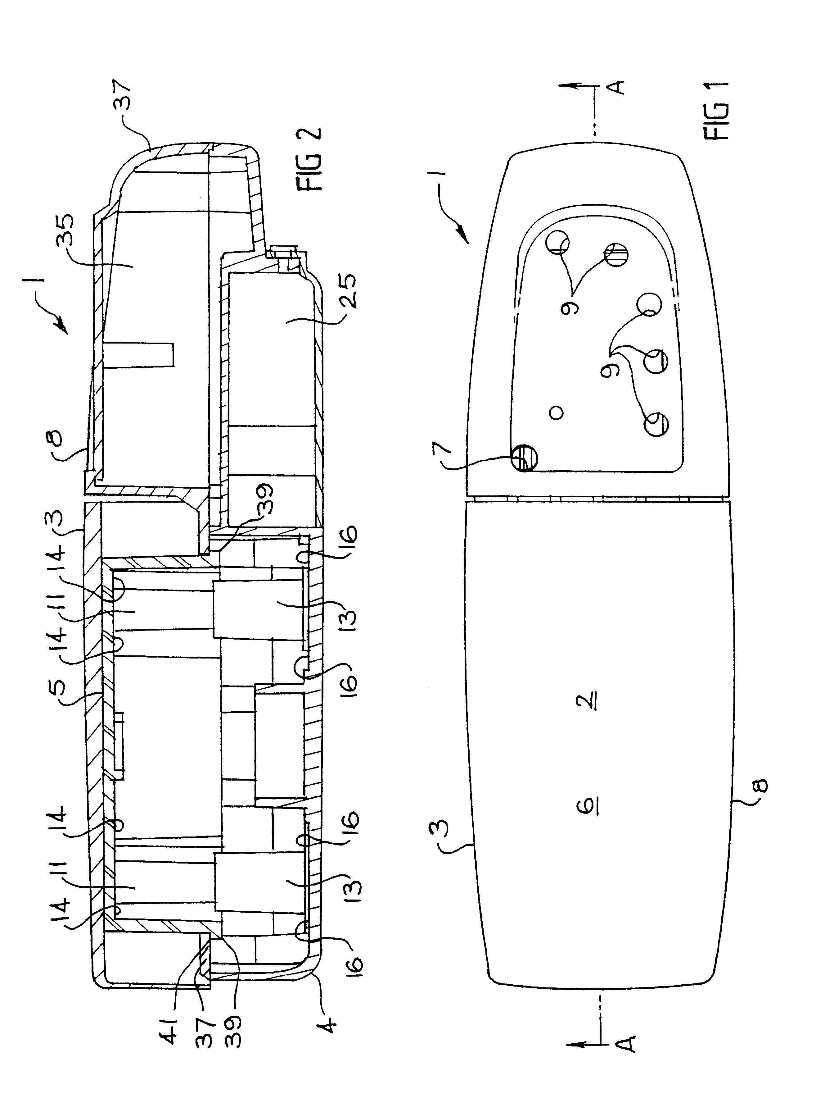
FIG. 1 shows a device 1 for monitoring cardiac compressions according to an example of an embodiment of the invention. The size of the device 1 is such that it can be located over a patient's sternum. Typically the size of the device 1 is such that its width is no greater than the width of a patients sternum. When the device 1 is in position overlying the sternum of a patient so that the length of the device lies along the length of the sternum and the width of the device extends across the sternum, a person can apply cardiac compressions to the patient by applying force to the body 8 of the device 1. That is to say, by locating the device 1 over the patient's sternum and applying force to the body 8, the user can ensure that no force is applied to the patient's ribs, thereby reducing the risk of breaking ribs which causes surgical complications in resuscitated patients. The user can monitor the application of cardiac compressions by applying cardiac compressions to area 2 of the up...


PUM


Abstract

Device (1) for monitoring cardiac compression being applied to a pateitn comprises a body to overlie and contact the sternum, preferably of width no greater than the width of the sternum. The device includes indidication means (9) responsive to the force applied to the body by the user for providing an indication of the cardiac compression applied to the sternum. Also disclosed is a resuscitation mask adapted to be place over the mouth of a patient, the mask includes a nostril closing means adapted to press against the sides of the nose to close the nostrils when the mask is sealed against the face of the patient.

Description

The present invention relates generally to methods and apparatus for use in cardio pulmonary resuscitation (CPR). More specifically the invention provides a device for monitoring cardiac compression being applied to a patient, a method of applying cardiac compression to a patient, a resuscitation mask, and a kit including a device for monitoring cardiac compressions and a resuscitation mask. The resuscitation mask may find broader application such as for use by anaesthetists during surgical procedures and the device for monitoring cardiac compression may also be used to train people in the application of cardiac compression.DESCRIPTION OF RELATED ARTEach year a large number of persons suffer cardiac and / or respiratory failure. Most of these instances of cardiac and respiratory failure occur outside of the presence of trained medical personnel. However, it is important for CPR to be applied as soon as possible to provide the person who suffers cardiac and / or respiratory failure the b...

Claims


Application Information

Patent Timeline
Patent Type & Authority Patents(United States)
IPC IPC(8): A61H31/00A61M16/00A61M16/06
CPCA61H31/005A61H31/007A61M16/0048A61H2201/018A61H2201/107A61M2205/43A61H2201/5048A61H2201/5074A61M16/06A61H2201/5007
Inventor DAVARIS, ANDREWKARLIS, GEORGE
Owner MEDTEQ HLDG
Why Eureka
Try Eureka