Industrial multilayer textile

a multi-layer textile and textile technology, applied in the field of industrial textiles, can solve the problems of poor wet paper exfoliation in case of transferring wet paper to felt, further severe papering requirements, inferior wear resistance, etc., and achieve the effect of superior fiber supportability

Inactive Publication Date: 2005-03-01
NIPPON FILCON
View PDF16 Cites 45 Cited by
  • Summary
  • Abstract
  • Description
  • Claims
  • Application Information

AI Technical Summary

Benefits of technology

The present invention is in view of the above problem and to provide an industrial multilayer textile in which an upper surface side layer and a running surface side layer are connected and warp ground yarn connecting yarns forming part of an upper surface side surface are disposed in a set of two between upper surface side warps so as to form a plain weave texture corresponding to substantially one warp on a surface, by forming a plain weave surface by

Problems solved by technology

Further, in recent years, since a paper machine is made higher in speed, attendant upon it, also the requirement to the wire for papering becomes further severer.
If intrusion of a wet paper in the papermaking fabric becomes large, or sticking of a fiber is generated, also a problem that the wet paper exfoliation in case of transferring the wet paper to a felt becomes bad, arises.
However, since a fine mesh textile regarding the surfaceability and fiber supportability as important is fundamentally woven by yarns whose line diameters are small, it was inferior in wear resistance.
Furthermore, since the papermaking fabric runs at a high speed, on the r

Method used


Image

  • Industrial multilayer textile
  • Industrial multilayer textile
  • Industrial multilayer textile

Examples


example 1

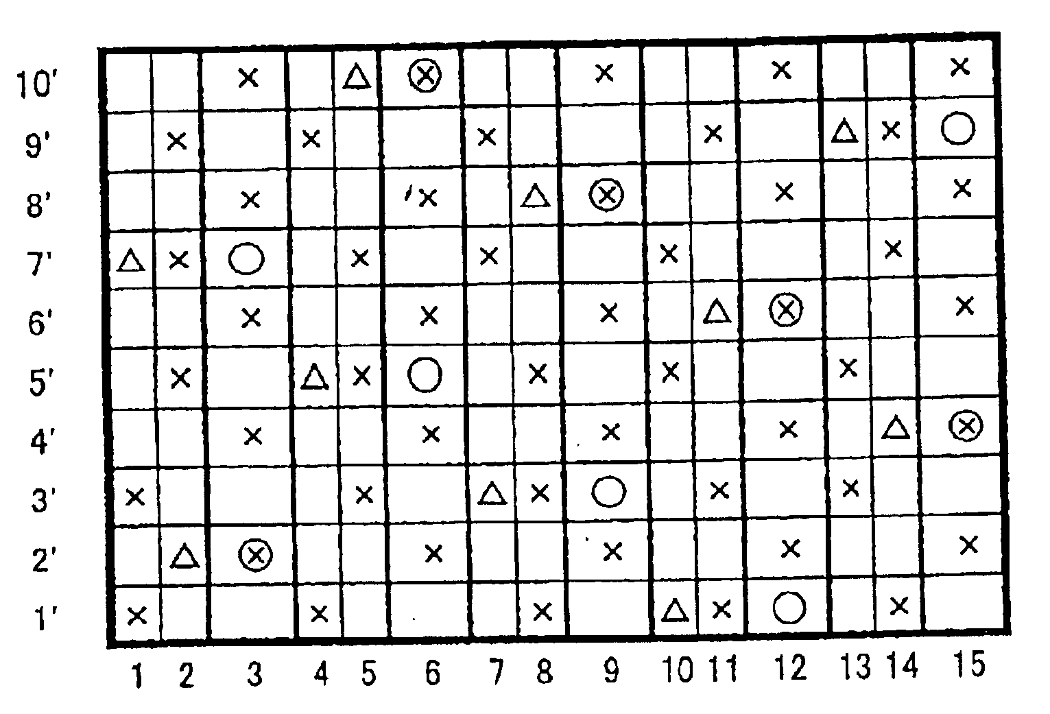
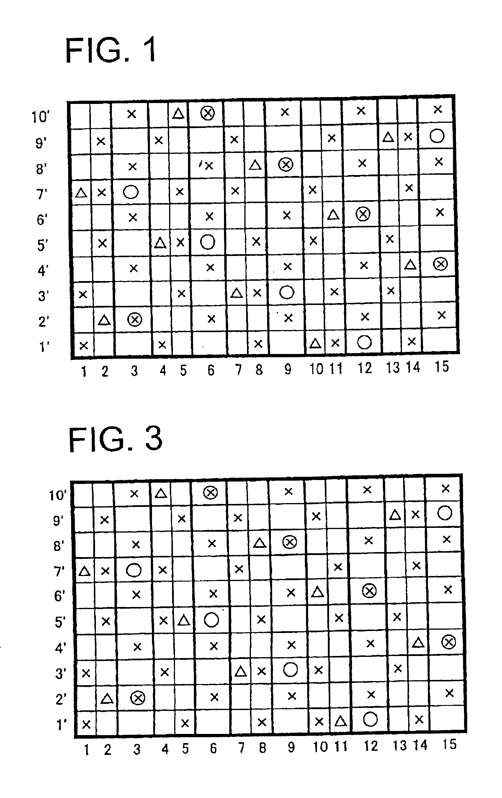
In the design view of FIG. 1, numerals 3, 6, 9, 12, and 15 denote upper surface side warps and running surface side warps that the upper surface side warps are disposed above the running surface side warps. Between the upper surface side warps and between running surface side warps, warp ground yarn connecting yarns are disposed in one set of two as 1 and 2, 4 and 5, 7 and 8, 10 and 11, and 13 and 14. Numerals with primes 1′, 2′, 3′, 4′, 5′, 6′, 7′, 8′, 9′, and 10′ denote wefts. Of these wefts, odd numbered upper surface side wefts 1′, 3′, 5′, 7′, and 9′ are first upper surface side wefts that pass under a warp ground yarn connecting yarn at a place shown with an x mark and do not pass under an upper surface side weft. Even numbered upper surface side wefts 2′, 4′, 6′, 8′, and 10′ are second upper surface side wefts that pass under an upper surface side warp at a place shown with an X mark and do not pass under a warp ground yarn connecting yarn. The upper surface side wefts are dis...

example 2

FIG. 3 showed another example of the present invention. The warp and weft of FIG. 3 are disposed in the same manner as those of Example 1, except for the one in which the order of one set of warp ground yarn connecting yarns is made alternate. In FIG. 1, the warp ground yarn connecting yarns in a pair of two different textures are present, each one of the warp ground yarn connecting yarns 1, 4, 7, 10 and 13 forms two knuckles on the upper layer surface (shown with marks of X), the other ones 2, 5, 8, 11 and 14 forms three knuckles (shown with marks of X), and those are disposed in the same order. However, in FIG. 3, the order of the first and second warp ground yarn connecting yarns are alternately changed or inversed, in that, first warp ground yarn connecting yarn of first pair forms two knuckles on the upper layer surface (e.g. the warp ground yarn connecting yarn 1) and second warp ground yarn connecting yarn of the first pair forms three knuckles (e.g. the warp ground yarn conn...

example 3

FIG. 4 is another example of the present invention. FIG. 4 is an 8-shaft two-layer textile, and the complete design view comprises four warps 3, 6, 9 and 12, and four sets of warp ground yarn connecting yarns 1 and 2, 4 and 5, 7 and 8, and 10 and 11. One set of two warp ground yarn connecting yarns is disposed between the warps. Examples 1 and 2 shown in FIGS. 1 and 3 have different textures of the warp ground yarn connecting yarns in one set. In the example 3, however, the textures of the warp ground yarn connecting yarns in one set are the same. On the textile surface, the texture of one set of two warp ground yarn connecting yarns forms a plain weave like one upper surface side warp. Concretely, the warp ground yarn connecting yarn 1 is in a texture in which it passes over one upper surface side weft 1′, passes between one upper surface side weft 2′ and the running surface side weft 2′, passes over one upper surface side weft 3′, passes between two upper surface side wefts 4′ and...


PUM


Abstract

An industrial multilayer textile has at least an upper surface side layer and a lower surface side layer as a running surface. The upper surface side layer and the lower surface side layer are connected by warp ground yarn connecting yarns that weave the upper surface side layer and the lower surface side layer. Among these, a pair of warp ground yarn connecting yarns is made into yarns corresponding to one warp in an upper surface side surface, and the pair of warp ground yarn connecting yarns and another warp are alternately disposed and woven with upper surface side wefts to form a surface of a substantially plain weave texture on the upper surface side layer.

Description

TECHNICAL FIELD OF THE INVENTIONThe present invention relates to industrial textiles such as textiles for papering, conveyor belts, and filter cloths.BACKGROUND OF THE INVENTIONHitherto, as industrial textiles, textiles woven by warps and wefts are widely used, for example, they are used in many fields other than a papermaking fabric, a belt for conveyance, a filter cloth, and so on, and textile characteristics suitable for applications and use environments are required. In particular, the requirement in the wire for papering used in a papermaking step in which sucking of a material or the like is performed using a mesh of a textile, is severe, a textile superior in surfaceability in which no wire mark of the textile is transferred to a paper, besides, one having together a rigidity of a degree in which it can be suitably used even under a severe environment, and a textile which can keep, for a long period, conditions necessary for manufacturing a good paper, are requested. Other th...

Claims


Application Information

Patent Timeline
IPC IPC(8): D03D11/00D21F1/00D03D1/00D21F1/10
CPCD21F1/0045D03D11/00Y10T442/3179
Inventor KUJI, TAKEHITO
Owner NIPPON FILCON
Why Eureka
Try Eureka