Router plunge depth adjustment mechanism

a plunge and depth adjustment technology, applied in the field of hand tools, can solve the problems of difficulty in adjusting the maximum depth of cut, previous coarse adjustment mechanisms that do not permit easy access, etc., and achieve the effect of accurate depth adjustment and easy operation

Inactive Publication Date: 2005-03-08
BLACK & DECKER INC
View PDF40 Cites 31 Cited by
  • Summary
  • Abstract
  • Description
  • Claims
  • Application Information

AI Technical Summary

Benefits of technology

Accordingly, the present invention is directed to an apparatus and method for providing plunge router depth adjustment, such as when a router is utilized with a table. The apparatus and method of the present invention permits easy, accurate depth adjustment from the base end of a router or when a router is utilized with a table.

Problems solved by technology

Difficulties may occur when a user wishes to utilize plunge routers with a router table.
Adjusting the maximum depth of cut may be difficult when using a router table because the table extends beyond the router base to support the workpiece.
Previous coarse adjustment mechanisms fail to permit ease of access.
For example, a coarse adjustment mechanism such as a set screw or thumb screw may be difficult to adjust when the plunge router is orientated with the motor housing in a downward direction, such as when mounted under a table.
Additionally, coarse adjustment mechanisms utilizing screws may be difficult to secure while the user is attempting to adjust the router against a spring while setting the coarse plunge mechanism.
Additionally, providing plunge depth adjustment from a base end is problematic.
For instance, a depth adjustment mechanism disposed in or connected to the router base may cause difficulties or prohibit switching base plates.
Adjustment mechanisms, and particularly fine adjustment mechanisms, connected to the base may become damaged, fouled with debris such as sawdust, and the like.
Adjustment mechanisms mounted to the base may increase manufacturing expense.
An adjustment mechanism permitting adjustment for the base end may not permit ease of adjustment from the motor housing end, for example when a plunge router is disposed with the motor housing orientated upwardly.
Removing the router from the table may be time consuming.
Attempting to change router depth, while the router is mounted under the table, may be difficult and lead to imprecision and user dissatisfaction.
Previous router devices fail to provide accurate depth adjustment.

Method used


Image

  • Router plunge depth adjustment mechanism
  • Router plunge depth adjustment mechanism
  • Router plunge depth adjustment mechanism

Examples


Embodiment Construction

Reference will now be made in detail to the presently preferred embodiments of present invention, examples of which are illustrated in the accompanying drawings.

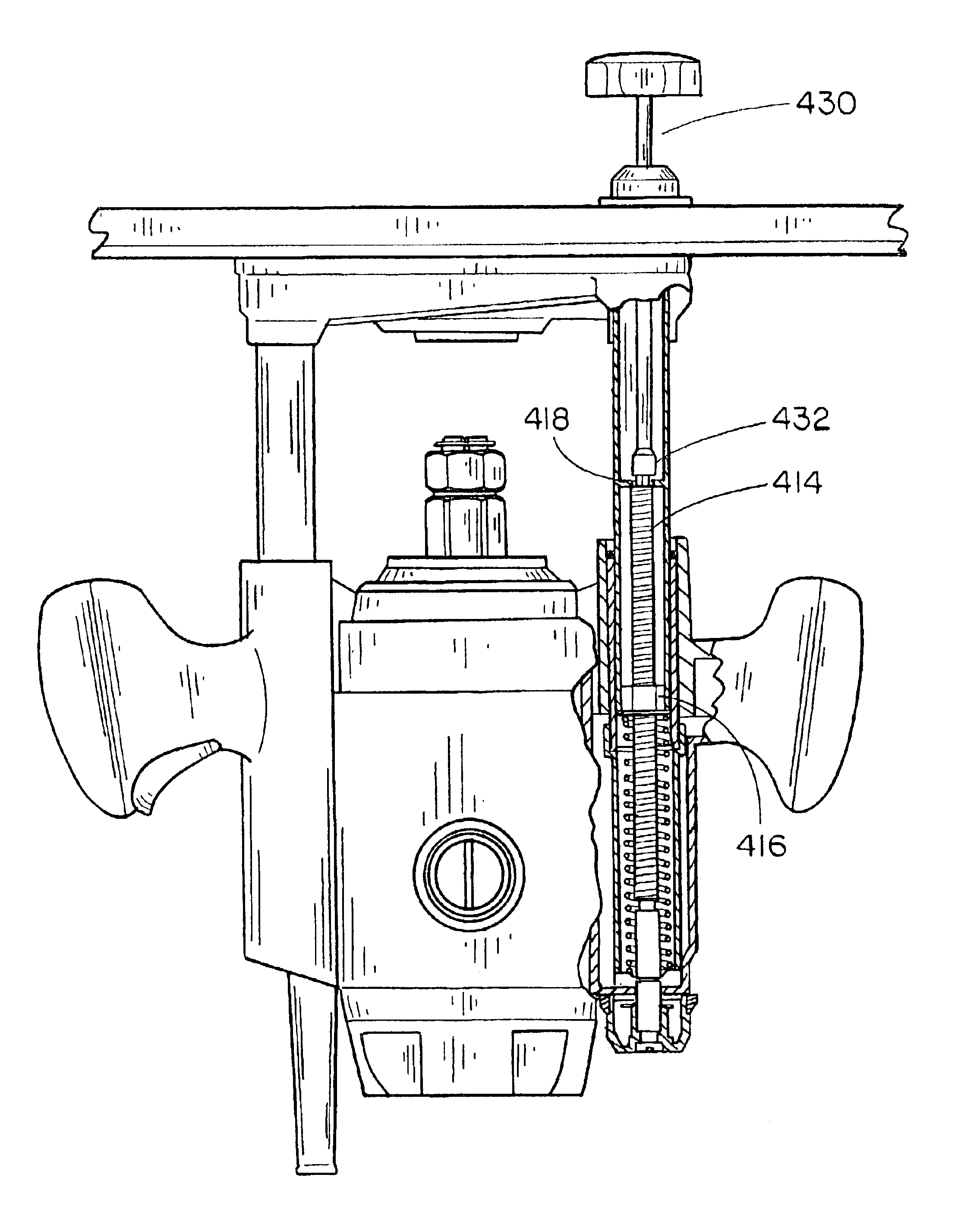
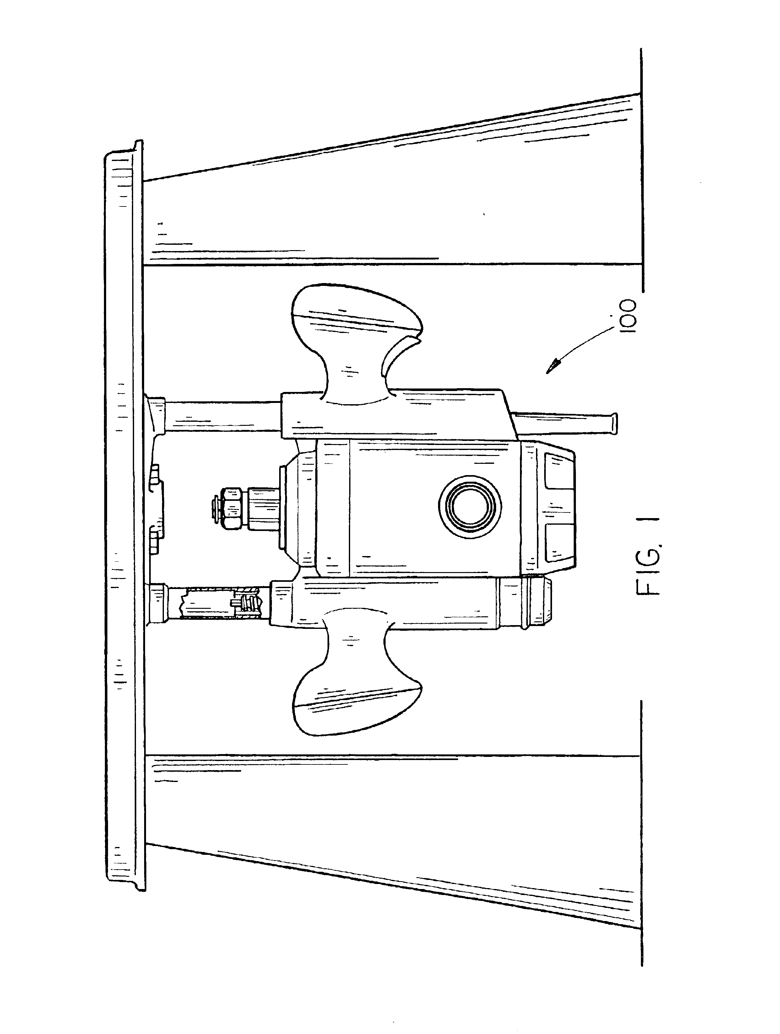
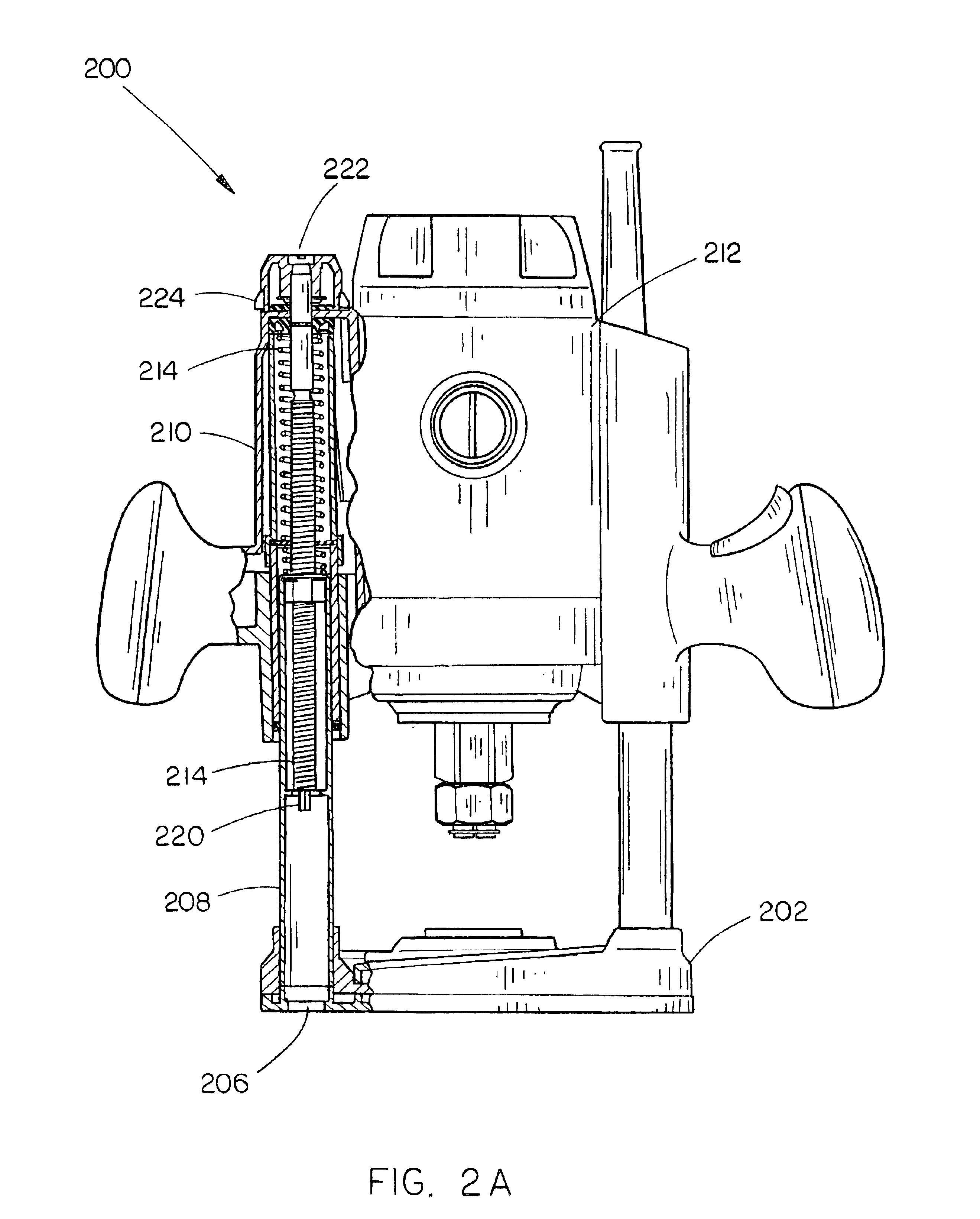
Referring generally now to FIGS. 1 through 7, exemplary embodiments of the present invention are shown. The system and method of the present invention overcome the difficulties associated with typical plunge router adjustment mechansims, such as plunge router is utilized with a router table.

Referring to FIGS. 1, 2A and 2B, a mechanism 200 of the present invention is suitable for utilization in a plunge router 100. The mechanism 200 for permitting base end plunge depth adjustment of a router is shown. A base 202 is included in the mechanism 200. The base 202 contains an aperture 206 suitable for permitting access to the interior of a first column portion 208 connected to the base 202. For example, the aperture 206 is sufficient to allow a wrench, such as an Allen wrench to access the interior recess of the first column portio...


PUM

PropertyMeasurementUnit
depthaaaaaaaaaa
mechanicalaaaaaaaaaa
depth of cutaaaaaaaaaa

Abstract

The present invention is directed to a mechanism and method for providing base end plunge router depth adjustment, such as when a router is utilized with a router table. The apparatus and method of the present invention permits accurate and efficient depth adjustment when utilizing a router with a router table. A router depth adjustment device includes an adjustment knob and indexer, so users are provided with the ability for measured depth adjustment.

Description

FIELD OF THE INVENTIONThe present invention relates to the field of hand tools and particularly to an apparatus and method for permitting plunge router depth adjustment from a base end.BACKGROUND OF THE INVENTIONPlunge routers utilize various systems for changing the maximum depth to which the bit will advance. Typically, depth adjustment systems are mounted to permit ready access when the router is orientated with the motor housing orientated upwardly. Difficulties may occur when a user wishes to utilize plunge routers with a router table. When a plunge router is utilized with a router table, the router is orientated with the motor housing in a downward direction. Adjusting the maximum depth of cut may be difficult when using a router table because the table extends beyond the router base to support the workpiece.For instance, plunge routers may include a coarse adjustment mechanism to permit large changes in the maximum depth of cut and a fine adjustment mechanism. Previous coarse...

Claims


Application Information

Patent Timeline
Patent Type & Authority Patents(United States)
IPC IPC(8): B23C1/00B23C1/20B27C5/02B27C5/10
CPCB27C5/02B27C5/10Y10T409/308176Y10S81/05Y10T409/30924Y10T409/308624Y10T409/306608
Inventor TAYLOR, MIKE
Owner BLACK & DECKER INC
Why Eureka
Try Eureka