Mail container with contaminant indicator

a technology of contaminant indicators and mail containers, applied in the field of mail containers, can solve the problems of increasing the risk of receiving biologically contaminated mail

Inactive Publication Date: 2005-03-15
WOOD JAMES T
View PDF13 Cites 10 Cited by
  • Summary
  • Abstract
  • Description
  • Claims
  • Application Information

AI Technical Summary

Problems solved by technology

The threat of receiving biologically contaminated mail has increased due to the increasing use of terrorist tactics by groups and individuals seeking to further their political agendas.

Method used


Image

  • Mail container with contaminant indicator
  • Mail container with contaminant indicator
  • Mail container with contaminant indicator

Examples


Embodiment Construction

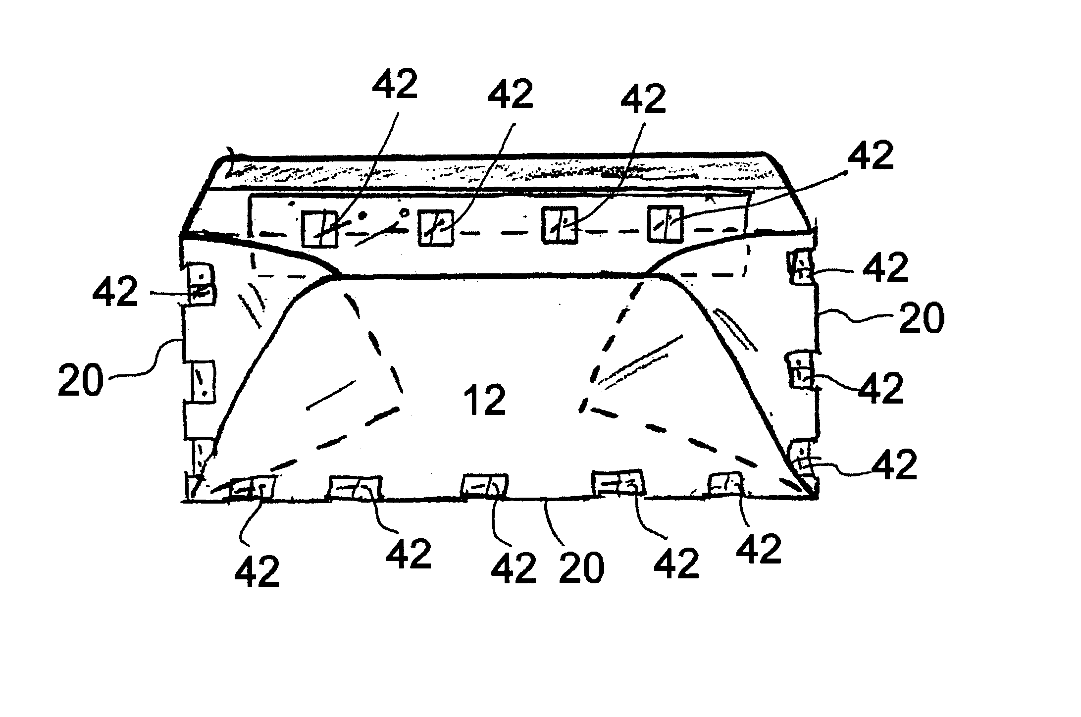
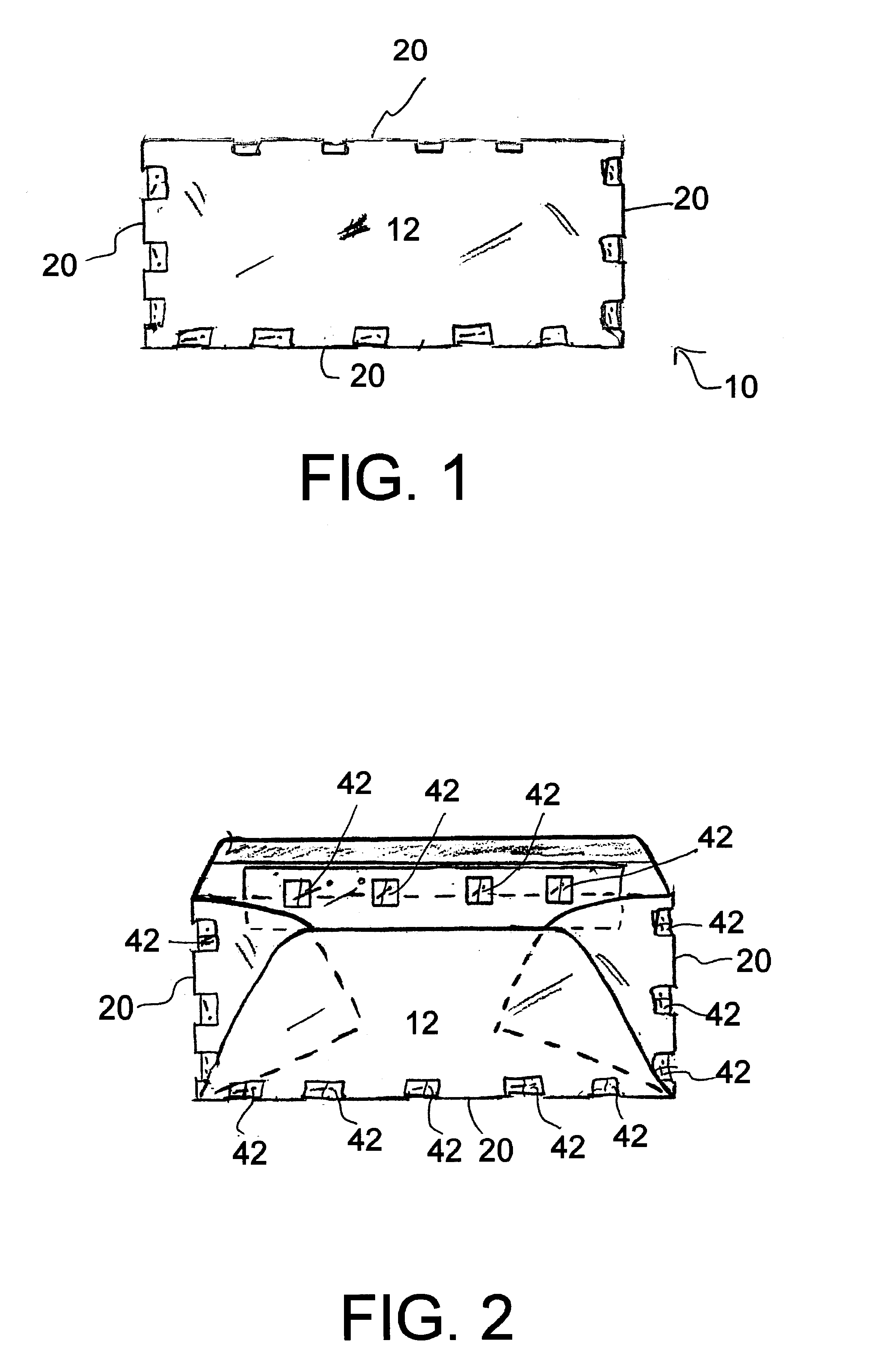
FIGS. 1-5 shows various aspects of exemplary embodiments of the mail container with contaminant indicator of the present invention generally designated 10,10a.

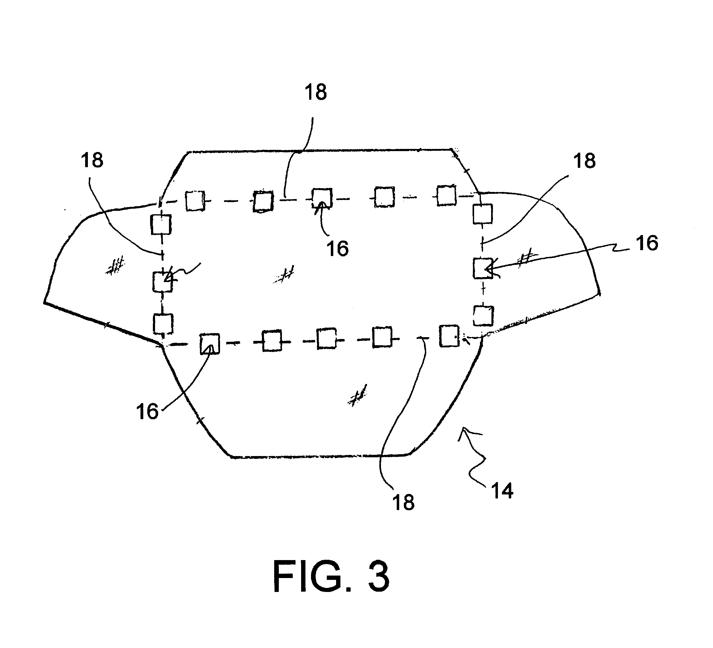
Mail container with contaminant indicator 10 is a legal sized envelope, generally designated 12, is formed from a die-cut paper blank, generally designated 14 (FIGS. 3,4) having contaminant viewing holes, generally designated 16, cut out across crease lines 18 along what will form the perimeter edges 20 of the envelope 12. Four clear plastic hole cover strips 38a-d are each permanently affixed to the paper blank 14 in a manner-to-sealing cover a number of the contaminant viewing holes 16 such that all the contaminant viewing holes 16 are sealed.

In this embodiment, one half of each section of plastic hole cover strip 38a-d covering each contaminant viewing hole 16 has an adhesive area 42 having a quantity of transparent, restickable adhesive provided thereon for trapping particulate contaminants for ready viewing by the mail c...


PUM


Abstract

A mail container with a contaminant indicator mechanism in the form of a perimeter edge viewing window is provided for verifying that a mail item received does not contain a biological hazard in the form of a loose particulate such as powders, granules, and the like. In order to attract the attention of the mail recipient that particulate matter may be contained in a mail container, an area having a quantity of clear, adhesive on only a portion of one or more of the transparent perimeter edge viewing windows so that the mail recipient or delivery person could immediately identify the existence of particulate matter contamination.

Description

TECHNICAL FIELDThe present invention relates to mail containers such as envelopes, mailing tubes, boxes, etc, and more particularly to a mail container with contaminant indicator that includes a transparent window provided along a perimeter edge of the mailing container for allowing a mail recipient to verify that the mail container is free from particulate contaminates such as powders, granules, particles, etc.BACKGROUND ARTThe threat of receiving biologically contaminated mail has increased due to the increasing use of terrorist tactics by groups and individuals seeking to further their political agendas. Because virtually everyone who receives mail is subject to such threats, it would be a benefit, particularly to advertisers and companies seeking to send legitimate correspondence, packages and the like to have a mail container with a contaminant indicator that could be used by legitimate individuals and companies which would provide the recipient of mail items with a mechanism f...

Claims


Application Information

Patent Timeline
Patent Type & Authority Patents(United States)
IPC IPC(8): B65D27/04B65D27/00
CPCB65D27/04B65D2203/00
Inventor WOOD, JAMES T.
Owner WOOD JAMES T
Why Eureka
Try Eureka