Disk drive employing a spindle motor comprising a locking spring arm disengaged through stator coil flux

a spindle motor and spindle motor technology, applied in the direction of mechanical equipment, instruments, record information storage, etc., can solve the problems of micro spots of fretting corrosion and exacerbate acoustic nois

Inactive Publication Date: 2005-03-15
WESTERN DIGITAL TECH INC
View PDF7 Cites 49 Cited by
  • Summary
  • Abstract
  • Description
  • Claims
  • Application Information

AI Technical Summary

Problems solved by technology

During shipping, vibrations may cause the spindle bearings to oscillate in small back and forth motions causing the bearings to push through the lubricating and anti-rust oil

Method used


Image

  • Disk drive employing a spindle motor comprising a locking spring arm disengaged through stator coil flux
  • Disk drive employing a spindle motor comprising a locking spring arm disengaged through stator coil flux
  • Disk drive employing a spindle motor comprising a locking spring arm disengaged through stator coil flux

Examples


Embodiment Construction

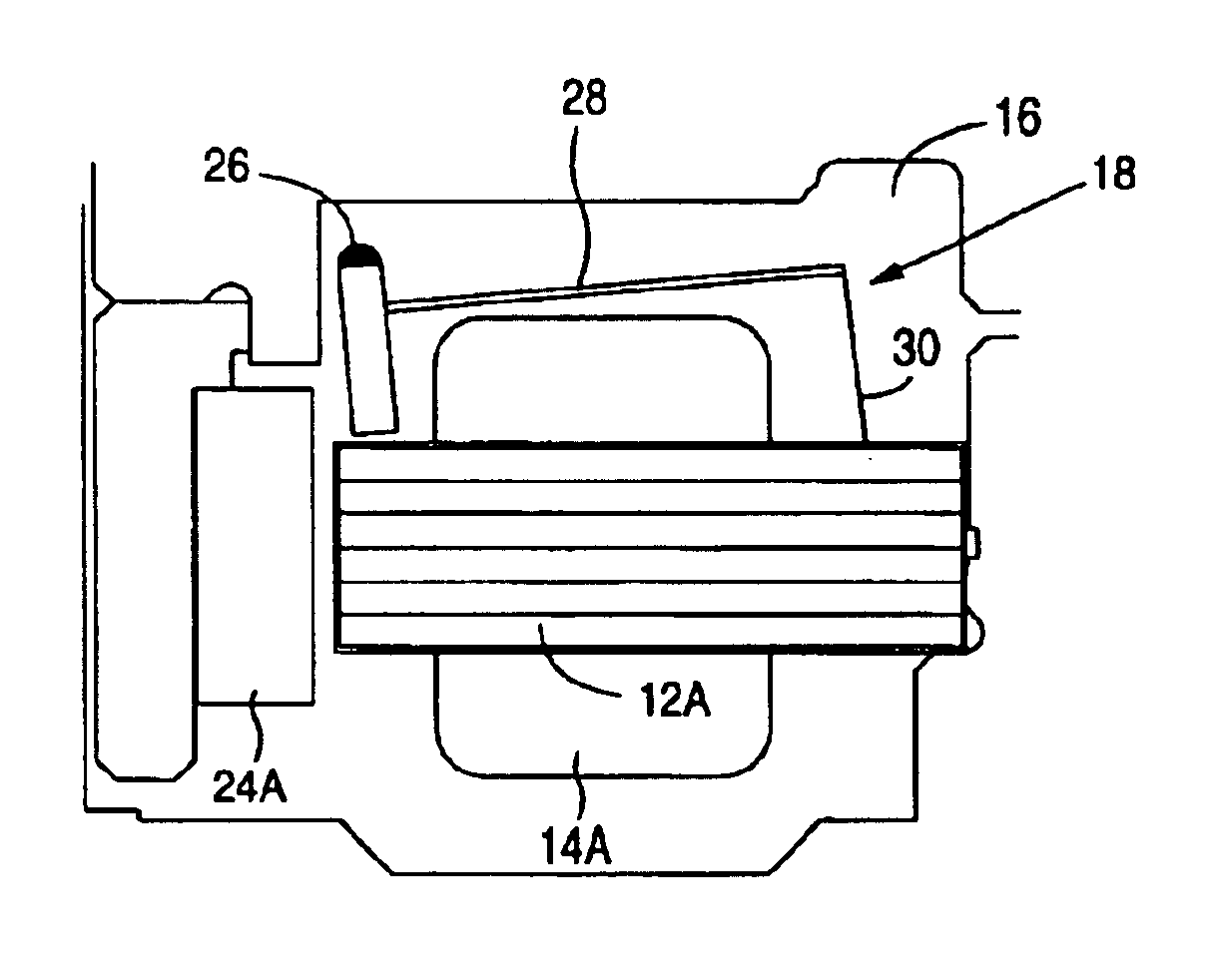
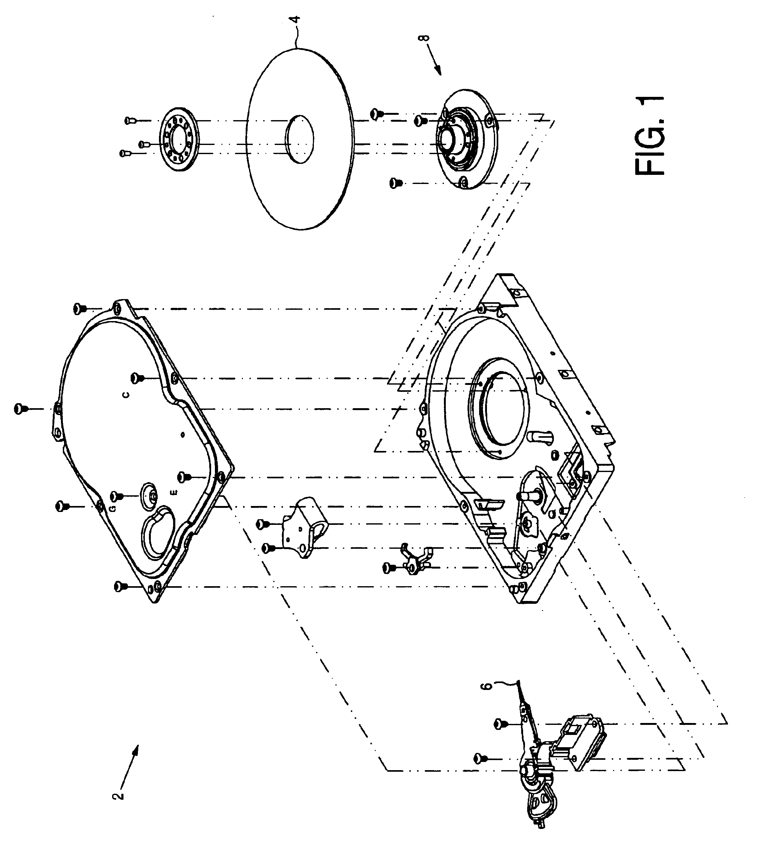
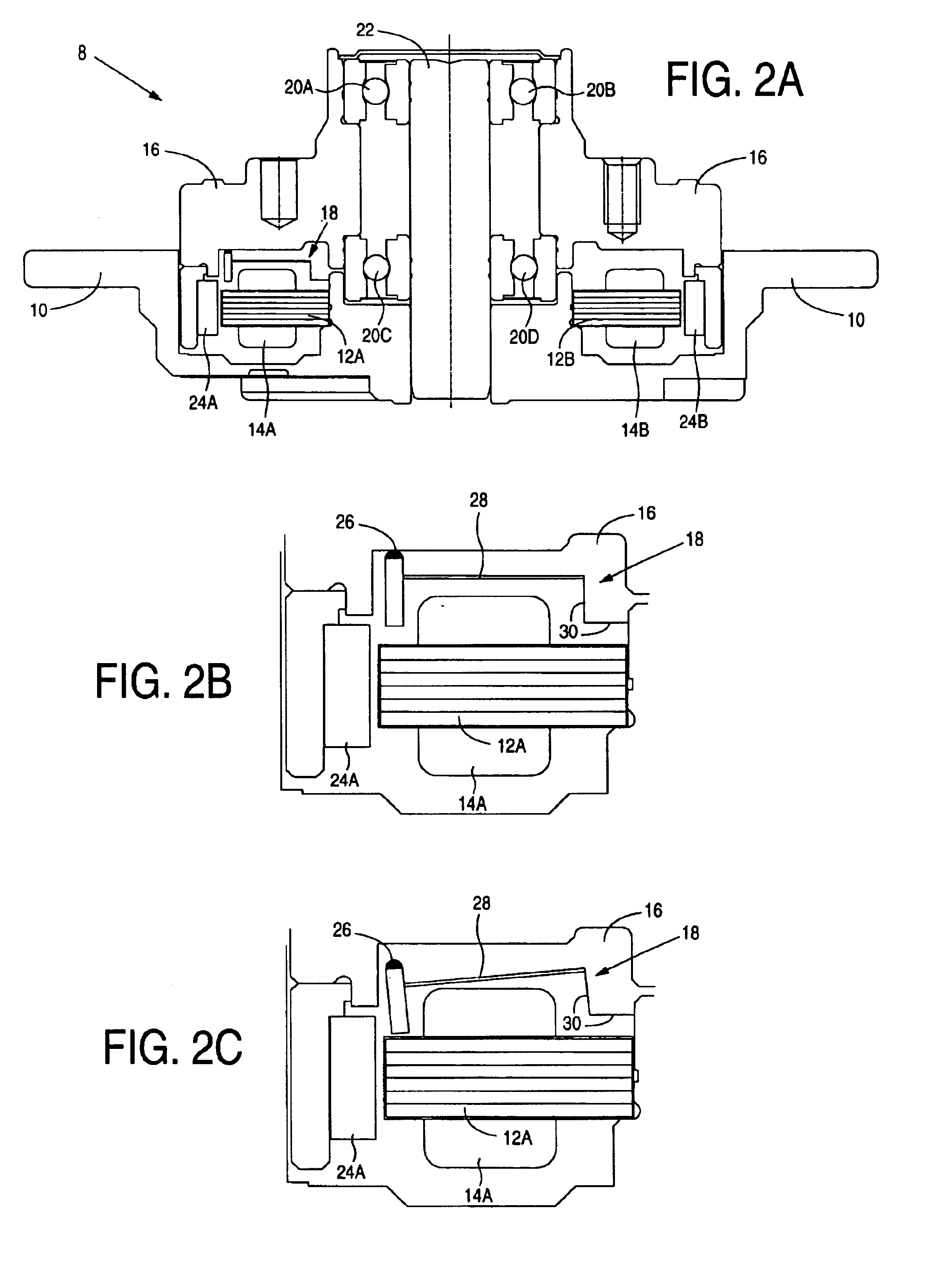
FIG. 1 is an exploded view of a disk drive 2 according to an embodiment of the present invention comprising a disk 4, a head 6 actuated radially over the disk 4, and a spindle motor 8 for rotating the disk 4. As shown in the cross-sectional view of FIG. 2A, the spindle motor 8 comprises a stator 10 having at least one stator coil 14A wrapped around a stator tooth 12A. The spindle motor 8 further comprises a hub 16 rotated by the stator 10 when current is applied to the stator coils, and a locking spring arm 18 having a fixed base. The locking spring arm 18 engages the hub 16 when no current is applied to the stator coil 14A, and the locking spring arm 18 disengages from the hub 16 when current applied to the stator coil 14A generates a magnetic flux which pulls the locking spring arm 18 away from the hub 16.

In the embodiment of FIG. 2A, the spindle motor 8 comprises bearings 20A-20D encased in lubricating and anti-rust oils. The bearings 20A-20D allow the hub 16 to rotate around a f...


PUM


Abstract

A disk drive is disclosed comprising a disk, a head actuated radially over the disk, and a spindle motor for rotating the disk. The spindle motor comprises a stator having at least one stator coil wrapped around a stator tooth. The spindle motor further comprises a hub rotated by the stator when current is applied to the stator coil, and a locking spring arm having a fixed base. The locking spring arm engages the hub when no current is applied to the stator coil, and the locking spring arm disengages from the hub when current applied to the stator coil generates a magnetic flux which pulls the locking spring arm away from the hub.

Description

BACKGROUND OF THE INVENTION1. Field of the InventionThe present invention relates to disk drives. More particularly, the present invention relates to a disk drive employing a spindle motor comprising a locking spring arm disengaged through stator coil flux.2. Description of the Prior ArtThe spindle motor within a disk drive typically employs high accuracy, low noise spindle bearings encased in lubricating and anti-rust oils. During shipping, vibrations may cause the spindle bearings to oscillate in small back and forth motions causing the bearings to push through the lubricating and anti-rust oils until there is metal-on-metal contact. The metal-on-metal contact creates micro spots of fretting corrosion which exacerbates acoustic noise and non-repeatable run-out NRRO).There is, therefore, a need for a disk drive which minimizes metal-on-metal contact of the spindle bearings due to vibrations during shipping.SUMMARY OF THE INVENTIONThe present invention may be regarded as a disk driv...

Claims


Application Information

Patent Timeline
IPC IPC(8): F16D65/14F16D63/00G11B19/20
CPCF16D63/006G11B19/2009F16D2121/22
Inventor BERDING, KEITH R.GUSTAFSON, JOHN R.
Owner WESTERN DIGITAL TECH INC
Why Eureka
Try Eureka