Method and apparatus for bottleneck feed factor based scheduling

a feed factor and bottleneck technology, applied in the field of manufacturing processes, can solve the problems of optimizing local wip movement, system scheduling lots that do not account for the current line dynamics in the manufacturing line, and rules that do not take into account the continuously changing dynamics of the manufacturing line, so as to maximize bottleneck throughput, promote manufacturing line linearity, and minimize bottleneck idle time. the effect of the idle tim

a feed factor and bottleneck technology, applied in the field of manufacturing processes, can solve the problems of optimizing local wip movement, system scheduling lots that do not account for the current line dynamics in the manufacturing line, and rules that do not take into account the continuously changing dynamics of the manufacturing line, so as to maximize bottleneck throughput, promote manufacturing line linearity, and minimize bottleneck idle time. the effect of the idle tim

US6868298B2Inactive Publication Date: 2005-03-15TEXAS INSTR INC

Image

  • Method and apparatus for bottleneck feed factor based scheduling
  • Method and apparatus for bottleneck feed factor based scheduling
  • Method and apparatus for bottleneck feed factor based scheduling

Examples


Embodiment Construction

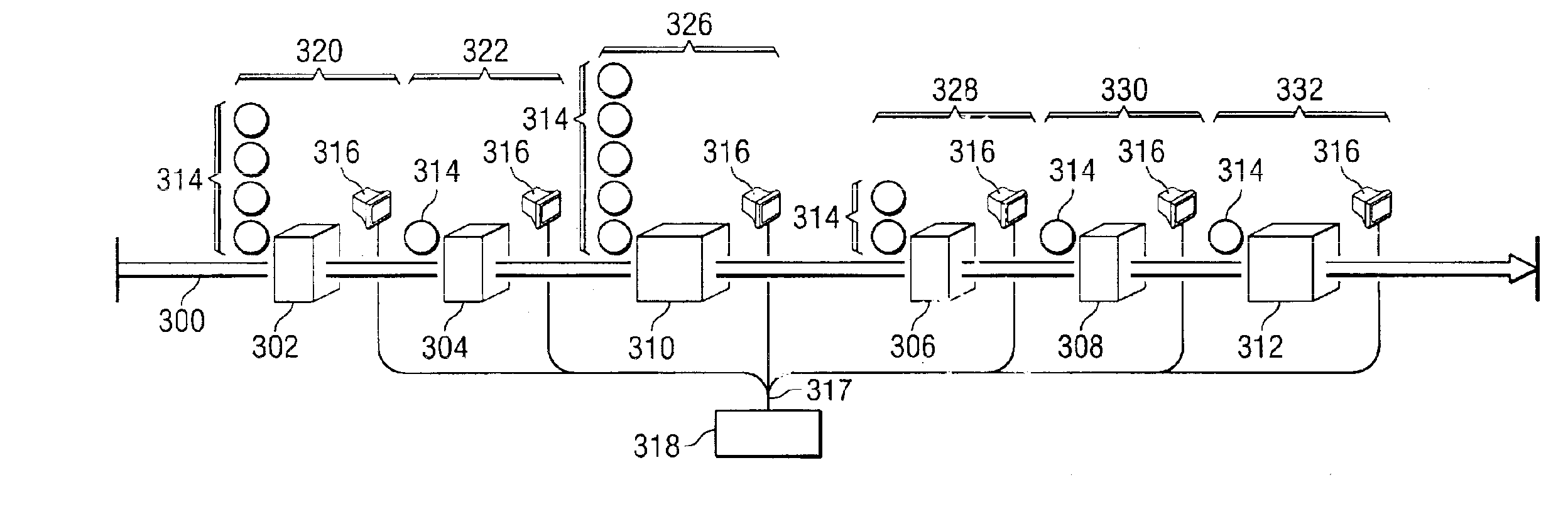
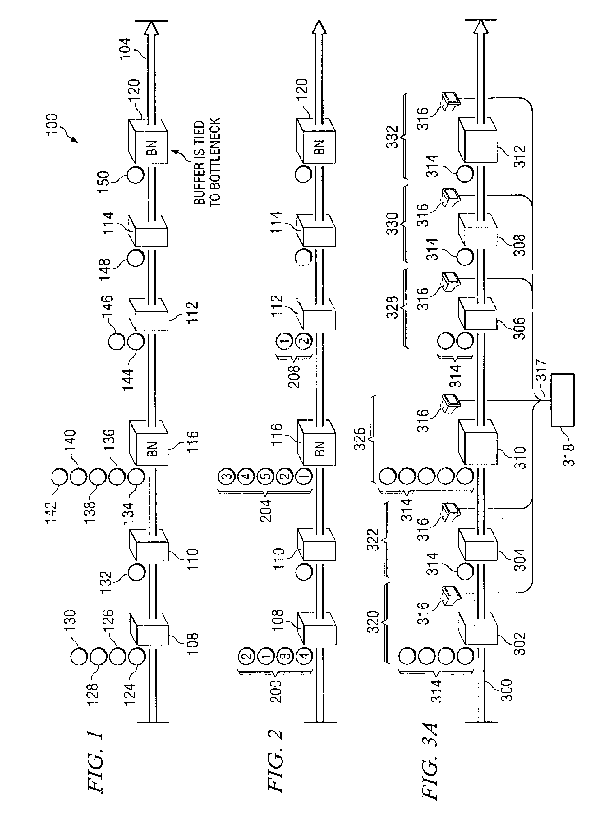
With reference now to the figures and in particular with reference to FIG. 1, therein is depicted system 100 for scheduling lots of items to be manufactured in accordance with one embodiment of the present invention. A manufacturing line 104 moving from left to right is shown. Tools and machines used in the manufacturing process are represented by small rectangular boxes 108, 110, 112 and 114. Tools and machines which are known for bottlenecks and are therefore referred to as “bottlenecks” are represented by larger boxes 116 and 120. The plurality of lots being manufactured are represented by circles 124-150.

Each lot 124-150 on the manufacturing line 104 has certain properties associated with it. One property is the planned cycle time (“PCT”). The PCT is the amount of time for a particular lot 124-150 to move through the next tool, the PCT includes the time required to machine the lot at the next tool, the processing time, the time to transport the lot, and any waiting time. The “PC...


PUM


Abstract

A method and system for scheduling lots for semiconductor manufacturing. The method and system comprising: determining a goal weighing factor (502); calculating the bottleneck feed factor for each lot in a tool queue (514); calculating the critical ratio for said each lot in a tool queue (516); calculating the relative rank of each lot in a tool queue; displaying the relative rank of each lot in a tool queue, for each tool queue; and selecting the lots in each tool queue for tooling according to said relative rank.

Description

TECHNICAL FIELD OF THE INVENTIONThe present invention relates generally to manufacturing processes such as those utilized in a semiconductor manufacturing environment and, more specifically, to apparatuses and methods for controlling the fabrication progress of semiconductor devices, including the production of lots through a manufacturing line.BACKGROUND OF THE INVENTIONManufacturers, such as but not limited to semiconductor manufacturers, continually strive to satisfy customer demands such as on-time delivery and lowest possible cost. Given the capital-intensive nature of the semiconductor industry, for instance, ever increasing capacity cost and longer lead-times, the manufacturing philosophy is to maximize output from its facilities while maintaining the minimum amount of Work-In-Progress (“WIP”). The scheduling of lots to fulfill the above goals is a real challenge in today's manufacturing environment of short product life cycles, complex product mix and shrinking time to marke...

Claims


Application Information

Patent Timeline
15 Mar 2005
Publication
US6868298B2
IPC
G05B19/418; G06Q10/00; G06Q10/06
CPC
G05B19/41865; G06Q10/06; G05B2219/45031; G05B2219/32266; Y02P90/02
Inventors
BAWEJA, GURSHAMAN; LA, HOA