Transparent optimization for transmission control protocol flow control

a transmission control protocol and transparent optimization technology, applied in data switching networks, instruments, frequency-division multiplexes, etc., can solve the problems of high packet loss, high congestion, network collapse, etc., to maximize the amount of data in transit, increase the window size, and minimize idle time

Active Publication Date: 2005-06-23
JUMIPER NETWORKS INC
View PDF13 Cites 48 Cited by
  • Summary
  • Abstract
  • Description
  • Claims
  • Application Information

AI Technical Summary

Benefits of technology

[0013] The present invention is a system and method for optimizing TCP's flow control without intruding upon TCP's core algorithms. The invention bi-directionally monitors the state of TCP flows on both sides of a network pipe. A control module relatively near a sender's local area network (LAN) automatically identifies a packet flow that has become latency-limited (or “window-limited”) based on TCP header information. After the packet flow has been identified as window-limited due to the network latency, the control module relatively near the sender's LAN and another control module relatively near a receiver's LAN optimize this packet flow by increasing the window size indicated in the receiver's acknowledgment packet. Both control modules operate synchronously to transparently manage the packet flow between the sender and the receiver. This transparent optimization process allows the sender to maximize the amount of data in transit, thereby substantially minimizing the idle times during which the sender is waiting for additional acknowledgments from the receiver.

Problems solved by technology

Multiple concurrent and reliable data transfers across a shared network link may result in high congestion if each of the data transfer sessions tries to fully utilize the link capacity.
This high congestion may result in high packet loss, which in turn may cause a large number of packet retransmissions, ultimately resulting in network collapse.
Network latency is a common problem that affects network and application performance.
Network latency is attributable to several factors, including physical distance, number of hops, switching and router relays, and network congestion.
Because these factors are not constants, networks may have unpredictable latency over a period of time.
In these applications, the common performance bottleneck is often the latency across the network, which causes lower application throughput via TCP.
In particular, the flow control algorithm within TCP often causes the lower application throughput and higher application response time.
Since the flow control algorithm prevents the sender from transmitting data to the receiver when the receiver has not indicated that it is ready for this additional data, long RTTs between the two endpoints may cause the sender to delay sending additional data packets to wait for the next acknowledgment from the receiver.
The latency-based TCP idle time may cause a single TCP flow to achieve lower throughput than is actually available on the network link.
This unused capacity translates into a higher transmission time since the TCP flow cannot utilize the full existing network bandwidth.
However, for practical reasons, this indicated window size may be limited by the available memory on the receiver and the sender.
But when a TCP connection is made across a high latency network, this value may not be adequate.
The computers participating in the data transfer cannot dynamically discover and fix the small window size problem.
This is because this problem can only be reliably observed by a device (which knows the bandwidth and current utilization of the long latency segment) processing data just before the longest latency segment of the network on the sender side.
However, after this device determines that a particular transfer is window-limited, TCP provides no means for the device to inform the receiver that an increased window size is desired.
A solution that arbitrarily has the device increase the window size produces poor results because it generates a large amount of out of window data.
Therefore, when there is a minor network error such as a single packet loss, this solution may cause a large amount of data that is outside of the receive window.
In addition to having the sender retransmitting the discarded data, it also causes the sender to misread the loss as a network congestion event and thus to slow down its transmission.

Method used


Image

  • Transparent optimization for transmission control protocol flow control
  • Transparent optimization for transmission control protocol flow control
  • Transparent optimization for transmission control protocol flow control

Examples


Embodiment Construction

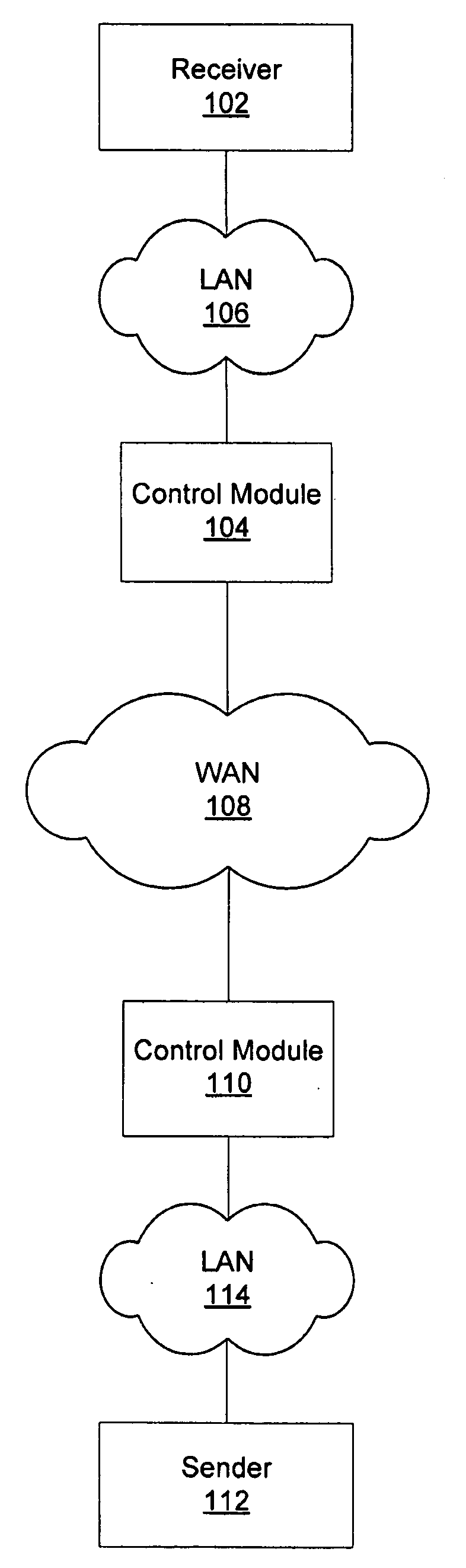
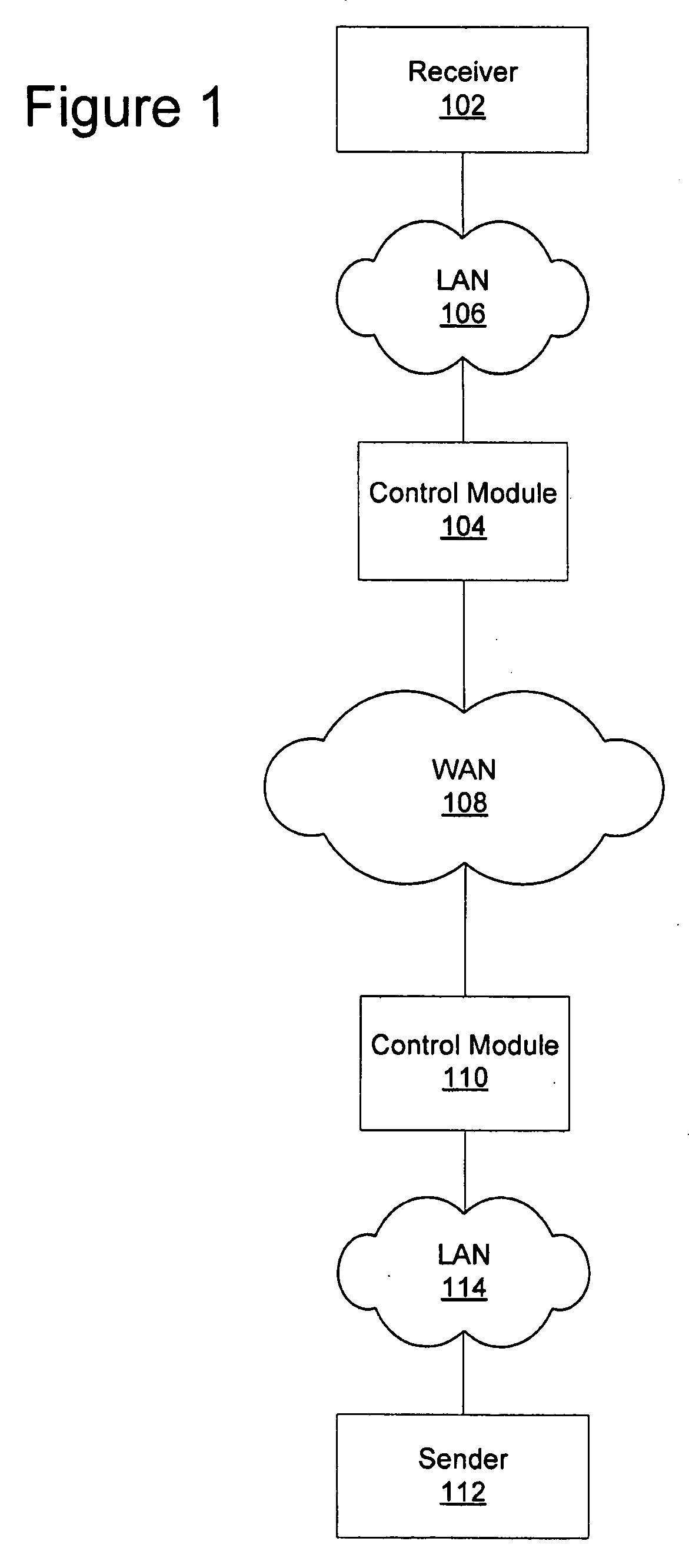
[0022] A preferred embodiment of the present invention is now described with reference to the figures where like reference numbers indicate identical or functionally similar elements. Also in the figures, the left most digit of each reference number corresponds to the figure in which the reference number is first used.

[0023] Reference in the specification to “one embodiment” or to “an embodiment” means that a particular feature, structure, or characteristic described in connection with the embodiments is included in at least one embodiment of the invention. The appearances of the phrase “in one embodiment” in various places in the specification are not necessarily all referring to the same embodiment.

[0024] Some portions of the detailed description that follows are presented in terms of algorithms and symbolic representations of operations on data bits within a computer memory. These algorithmic descriptions and representations are the means used by those skilled in the data proce...


PUM


Abstract

A system and method that optimizes transmission control protocol (TCP) flow control without intruding upon TCP's core algorithms. A control module relatively near a sender's local area network (LAN) automatically identifies a packet flow that has become window-limited. After the packet flow has been identified as window-limited, the control module relatively near the sender's LAN and another control module relatively near a receiver's LAN optimize the packet flow by increasing the window size indicated in the receiver's acknowledgment packet. Both control modules operate synchronously to transparently manage the packet flow between the sender and the receiver.

Description

RELATED APPLICATIONS [0001] This application claims priority from U.S. provisional application No. 60 / 517,934 filed on Nov. 5, 2003 which is incorporated by reference herein in its entirety. [0002] This application is related to U.S. patent application No. ______, filed on Nov. 4, 2004, entitled “Transparent Optimization for Transmission Control Protocol Initial Session Establishment”, the contents of which are hereby incorporated by reference.FIELD OF THE INVENTION [0003] The present invention relates to the field of networking and the communication of data over a network and more particularly to transparent optimization for transmission control protocol (TCP) flow control. BACKGROUND OF THE INVENTION [0004] The transmission control protocol (TCP) is one of the most widely used and reliable data transport protocols across communications networks. One of TCP's primary distinctions and the reasons for its widespread use is a robust algorithm to share bandwidth between current TCP ses...

Claims


Application Information

Patent Timeline
Patent Type & Authority Applications(United States)
IPC IPC(8): H04LH04L1/00H04L47/27
CPCH04L47/10H04L47/193H04L69/163H04L69/16H04L47/27
Inventor SINGH, BALRAJSINGH, AMIT P.PAXSON, VERN
Owner JUMIPER NETWORKS INC
Why Eureka
Try Eureka