Method and apparatus for determining the angle of gyration and/or the pressure in a gyratory compactor

a gyratory compactor and angle measurement technology, applied in the direction of material strength using tensile/compressive forces, instruments, magnetic variables, etc., can solve the problems of large time and money expenditure, inability to re-calibrate in a static mode, and inability to accurately measure the angle of gyration and/or pressure in the gyratory compactor field

Inactive Publication Date: 2005-03-22
TROXLER ELECTRONICS LAB INC
View PDF15 Cites 106 Cited by
  • Summary
  • Abstract
  • Description
  • Claims
  • Application Information

AI Technical Summary

Benefits of technology

Thus, embodiments of the present invention provide apparatuses, devices, systems, and methods capable of statically and dynamically determining and indicating the angle of gyration of a mold as well as a pressure exerted on a sample contained therein so as to provide a consistent and read

Problems solved by technology

However, a calibration carried out in a static mode will not necessarily take into account whether the configuration of the gyratory compactor maintains the mold angle within specifications throughout the entire compaction process.
However, the correct angle typically can only be verified by a complete re-calibration of the machine and such a re-calibration is often not practical in the field.
As such, re-calibration usually requires that the machine be shipped back to the manufacturer, or requires the presence of a factory technician at the site, each of which may involve a sizeable expenditure of time and money.
Accordingly, the plungers may be prone to wear or misalignment from

Method used


Image

  • Method and apparatus for determining the angle of gyration and/or the pressure in a gyratory compactor
  • Method and apparatus for determining the angle of gyration and/or the pressure in a gyratory compactor
  • Method and apparatus for determining the angle of gyration and/or the pressure in a gyratory compactor

Examples


Embodiment Construction

The present invention now will be described more fully hereinafter with reference to the accompanying drawings, in which preferred embodiments of the invention are shown. This invention may, however, be embodied in many different forms and should not be construed as limited to the embodiments set forth herein; rather, these embodiments are provided so that this disclosure will be thorough and complete, and will fully convey the scope of the invention to those skilled in the art. Like numbers refer to like elements throughout.

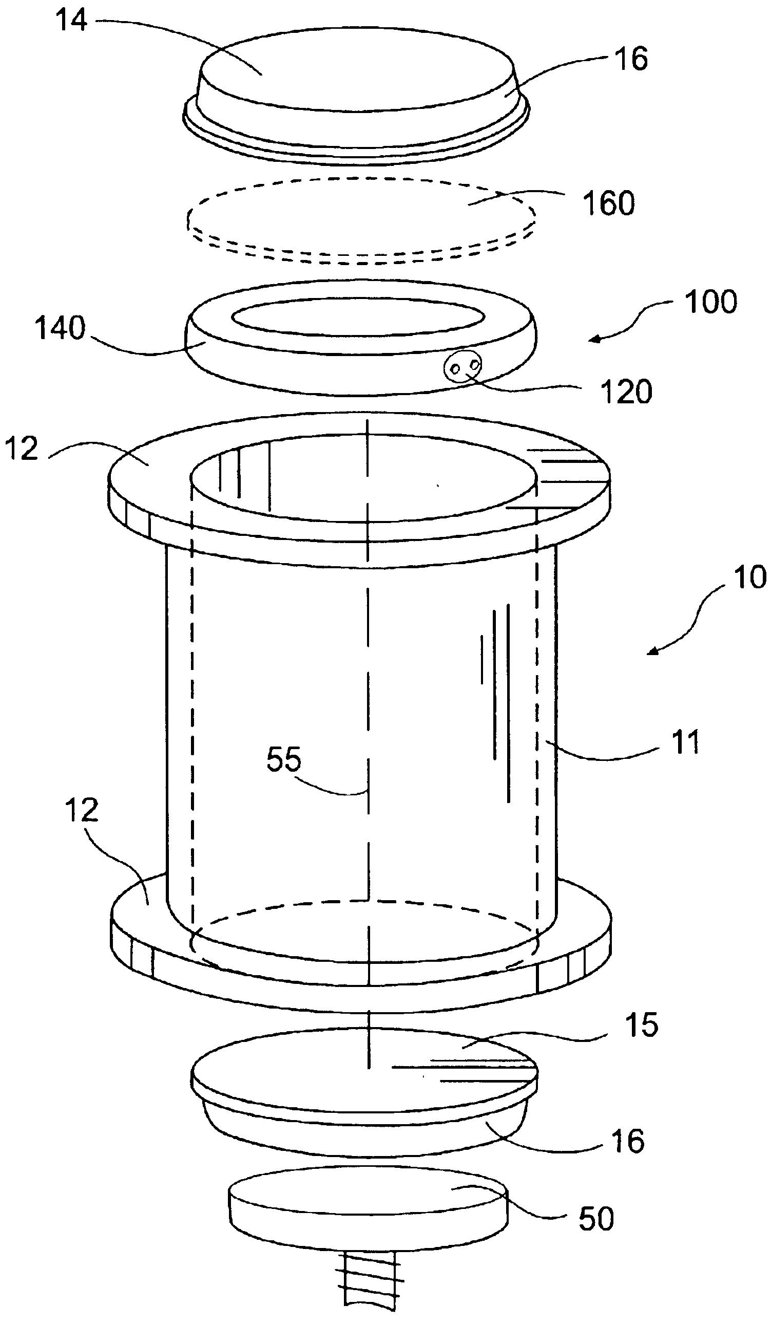
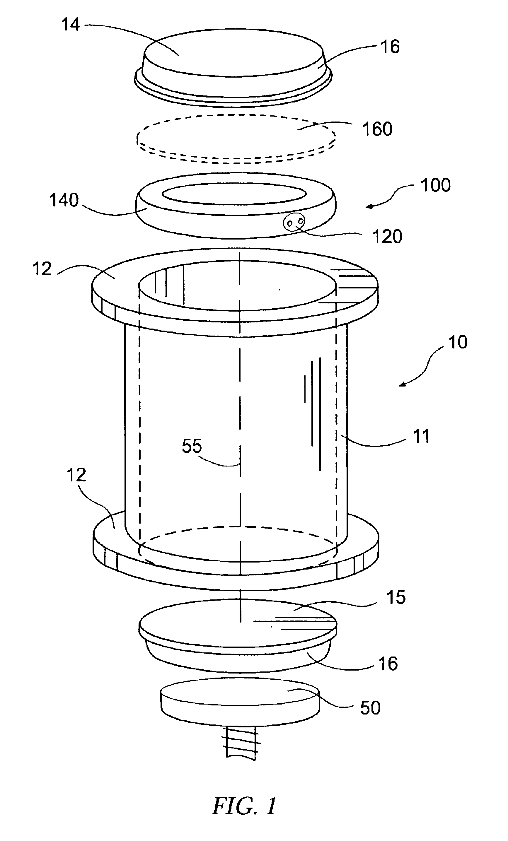
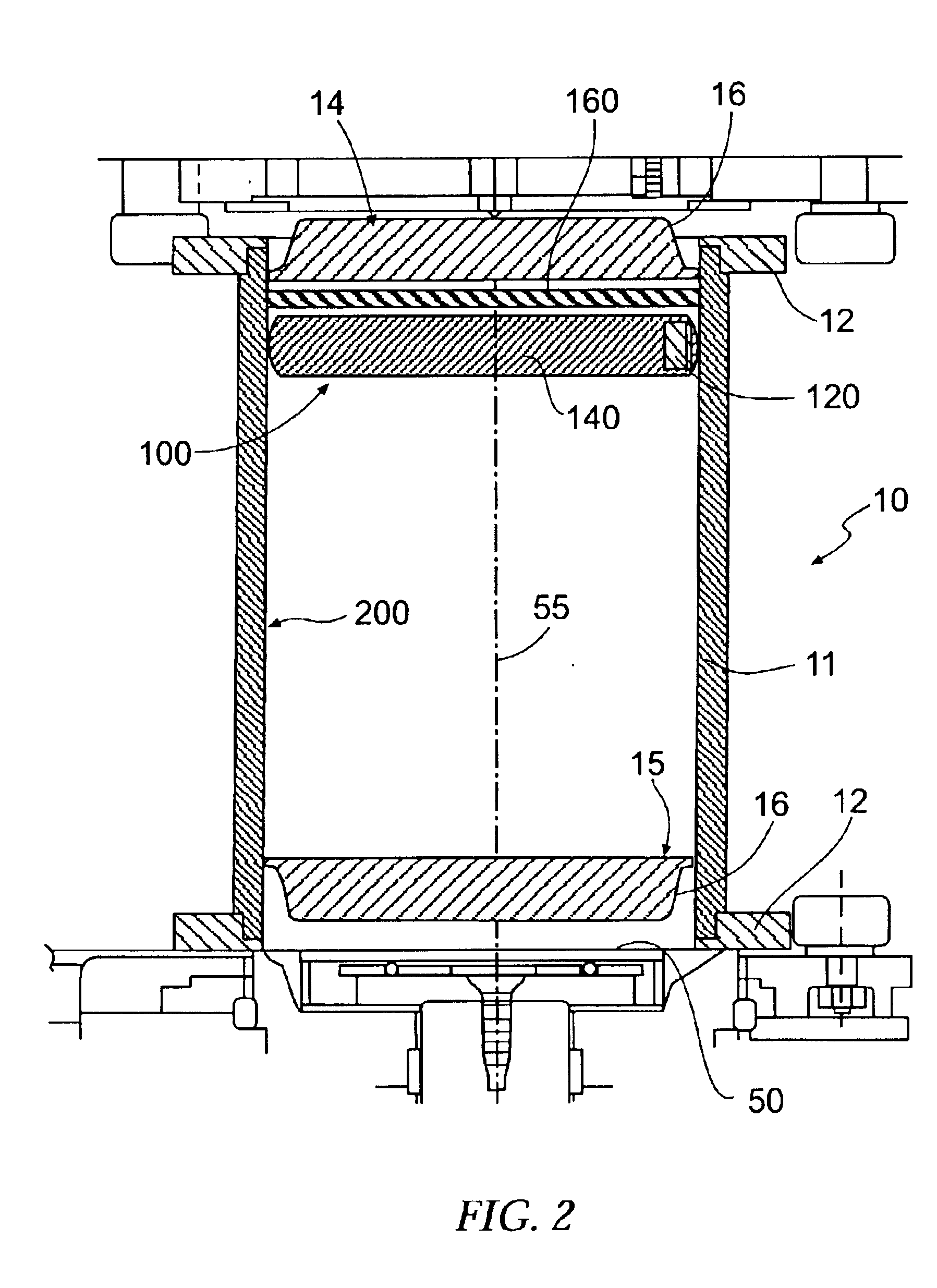
A gyration angle measurement device according to the present invention is designed to be used with any of the Superpave gyratory compactors which are presently available commercially. Illustrative but non-limiting examples of gyratory compactors which can utilize such a gyration angle measurement device of the present invention are described in the following U.S. Pat. Nos. 5,323,655; 5,456,118; 5,606,133; 5,939,642; 5,817,946; and 6,026,692.

FIGS. 1 and 2 illustr...


PUM


Abstract

An apparatus adapted to interact with a cylindrical mold for a gyratory compactor so as to determine a property of the gyratory compactor is provided, wherein the mold is adapted to contain a sample therein. Such an apparatus comprises a rigid disk-shaped plate defining an axis and a periphery, with the plate being adapted to be disposed within the mold. At least one sensing device is operably engaged with the plate, wherein the at least one sensing device is configured to measure a proximity of the at least one sensing device with respect to a reference member and to produce a corresponding signal indicative of the property of the gyratory compactor. In one embodiment, the apparatus is configured to determine the gyration angle of the mold, while in another embodiment, the apparatus is configured to determine the pressure exerted on the sample within the mold. The property of the mold may be determined either statically or dynamically. Associated apparatuses, devices, systems, and methods are also provided.

Description

BACKGROUND OF THE INVENTION1. Field of the InventionThe present invention relates to a device for measuring a property of a gyratory compactor device and, more particularly, to a method and apparatus for determining an angle of gyration and / or a pressure in a Superpave gyratory compactor.2. Description of Related ArtThe Strategic Highway Research Program (SHRP) has developed a standard for testing the physical properties of a bituminous asphalt paving mix, using a device known as the Superpave gyratory compactor. The Superpave gyratory compactor produces compacted cylindrical test samples of the asphalt paving mix for determining volumetric and mechanical properties. The compactor simulates the kneading action of the large rollers used to compact asphalt pavement during highway construction. Thus, the compacted samples simulate the density, aggregate orientation, and structural characteristics obtained in an actual roadway when proper construction procedures are used in the placemen...

Claims


Application Information

Patent Timeline
IPC IPC(8): G01N3/00G01N27/72G01N3/62G01N3/56G01N1/28G01N33/42G01N3/06
CPCG01N1/286G01N3/565G01N3/62G01N33/42G01N27/72G01N2203/0682G01N2203/0664
Inventor MOSCRIP, WILLIAM MATTHEWGOWAN, WILLIAM A.
Owner TROXLER ELECTRONICS LAB INC
Why Eureka
Try Eureka