Milling method

a milling method and milling technology, applied in the direction of driving apparatus, milling equipment, large fixed members, etc., can solve the problems of high tool wear, low cutting volume per unit time, high cost, etc., and achieve high cutting speed, moderate tool loading, and reduce tool wear.

Inactive Publication Date: 2005-03-22
MTU AERO ENGINES GMBH
View PDF23 Cites 39 Cited by
  • Summary
  • Abstract
  • Description
  • Claims
  • Application Information

AI Technical Summary

Problems solved by technology

In the case of the high-strength, difficult-to-cut materials customary for rotors in the construction of gas turbines, the said method has serious disadvantages, such as a low cutting volume per unit time, high tool wear, high costs and thus, ultimately, low economic viability.

Method used


Image

  • Milling method
  • Milling method
  • Milling method

Examples


Embodiment Construction

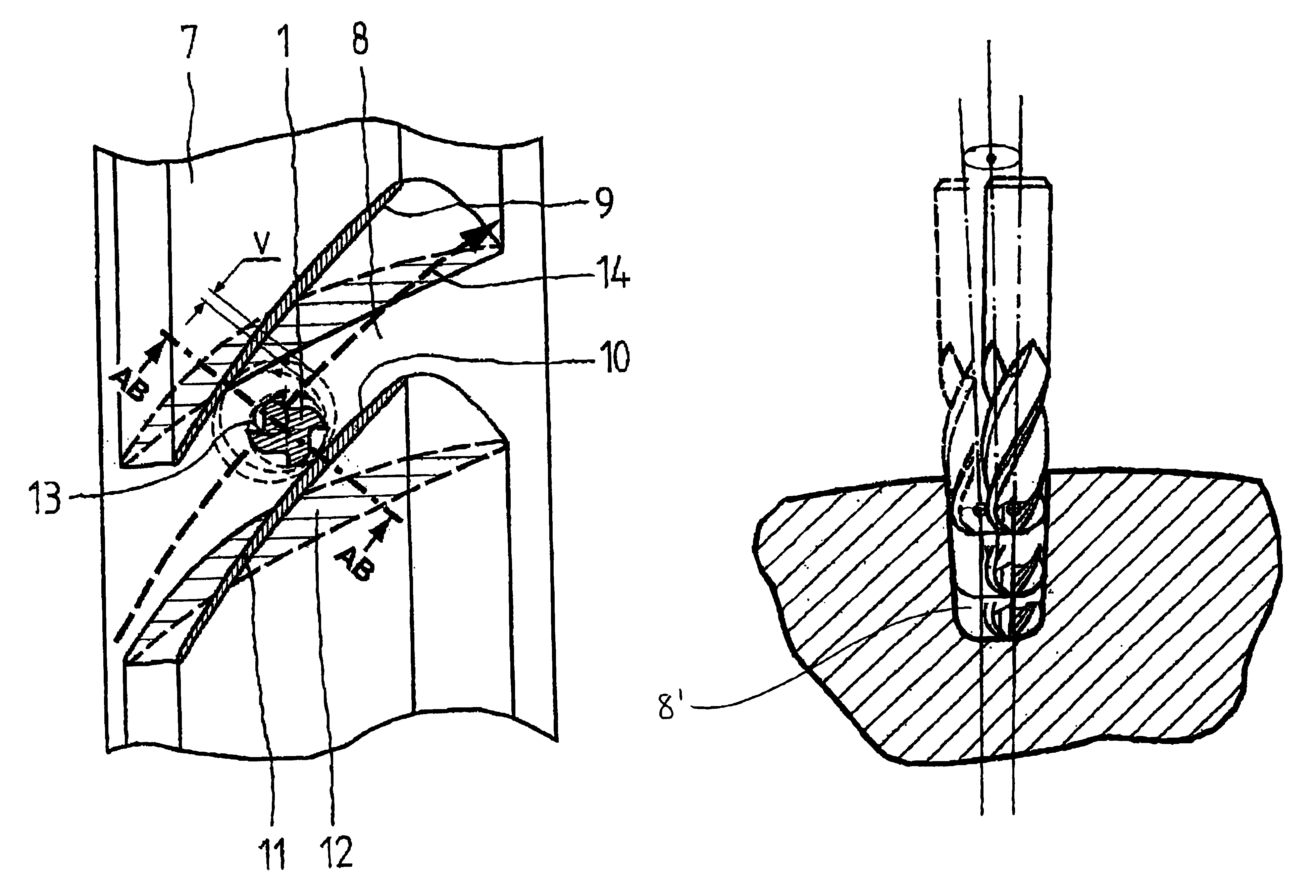
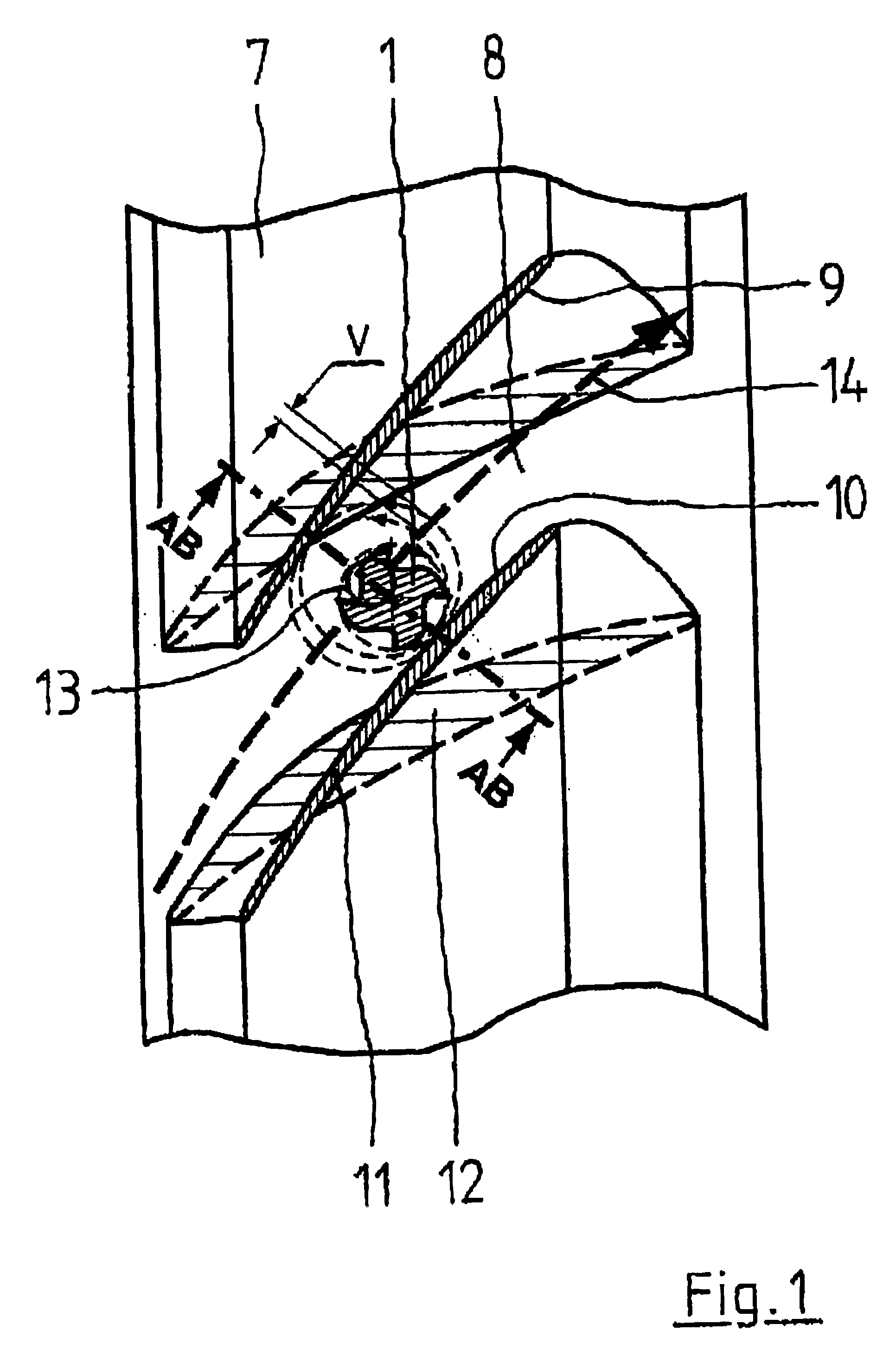
The component 7, here, by way of example, in the form of an axial-type gas turbine rotor to be provided with integral blades, is viewed approximately in the longitudinal direction of the milling tool 1 in FIG. 1. In the machining condition illustrated, a recess 8 is first of all produced between two opposite side walls 9, 10. In the final condition, a multiplicity of recesses 8 will be distributed uniformly over the periphery of the component, each separated by an identical number of blades. The recesses 8 then form the flow channels, while the side walls 9, 10 form the pressure and suction faces, respectively, of the blades. To facilitate understanding, blade profiles 11, 12 have been drawn in FIG. 1, 11 being intended to be the profile at the blade tip and 12 the profile at the blade root. It is clear from this that the side faces 9, 10 are three-dimensional surfaces with varying radii of curvature. This is intended to indicate that even very demanding contours can be produced wit...


PUM

PropertyMeasurementUnit
circumferenceaaaaaaaaaa
speedaaaaaaaaaa
transition radiusaaaaaaaaaa

Abstract

A milling method is provided for the manufacture of components composed of difficult-to-cut materials for turbomachines, aircraft and spacecraft by producing recesses with one or more side walls. An end milling cutter which cuts at the circumference and at the tip and has a tip contour which is rounded towards the circumference is used as the rotating milling tool. In addition to rotation about its axis, the milling tool performs an eccentric orbiting motion about an orbital axis spaced apart from its axis. The opposite senses of rotation lead to downcut milling, and the orbital axis performs a translational advance motion on a straight and / or curved path transversely to its longitudinal direction, with or without a swivelling motion.

Description

This application claims the priority of German application 102 19 012.7, filed Apr. 27, 2002, the disclosure of which is expressly incorporated by reference herein.BACKGROUND AND SUMMARY OF THE INVENTIONThis invention relates to a milling method for the manufacture of components composed of difficult-to-cut materials for turbomachines, aircraft and spacecraft.A milling method of this kind is known from U.S. Pat. No. 6,077,002. De facto, this patent provides rough machining by so-called full-cut parallel-stroke milling. In this process, a number of laterally offset grooves (rows) are generally milled, the machining of the respectively outermost grooves including the production of the side-wall contours. For this purpose, at least one milling tool which cuts at the tip and at the circumference is used, i.e. an appropriate end milling cutter. Deeper channels, including the multiple lateral groove offset, are machined in a number of feed steps in the longitudinal direction of the millin...

Claims


Application Information

Patent Timeline
Patent Type & Authority Patents(United States)
IPC IPC(8): B23C3/18B23C3/00
CPCB23C3/18B23C2220/366Y10T409/303808Y10T29/49995Y10T409/306328Y10T409/304424Y10T409/308232Y10T409/307112Y10T409/303136Y10T29/49336Y10T29/49325Y10T409/307616Y10T409/307672Y10T29/49332
Inventor LEBKUECHNER, GOETZ
Owner MTU AERO ENGINES GMBH
Why Eureka
Try Eureka