Chain link with angularly disposed end portions

a technology of end portions and chains, applied in the field of chains and chain links, can solve the problems of a large load on the hoisting and dragging chains and their links of such equipment, and the chain and chain links must be designed to endure a tremendous amount of wear, so as to increase the hardness of their outer surfaces and tensile strength

Inactive Publication Date: 2005-03-29
COLUMBIA STEEL CAST PROD LLC
View PDF15 Cites 35 Cited by
  • Summary
  • Abstract
  • Description
  • Claims
  • Application Information

AI Technical Summary

Problems solved by technology

The loads on the hoist and drag chains and their links of such equipment are massive.
In addition, these chains and chain links must be designed to endure a tremendous amount of wear.

Method used


Image

  • Chain link with angularly disposed end portions
  • Chain link with angularly disposed end portions
  • Chain link with angularly disposed end portions

Examples


first embodiment

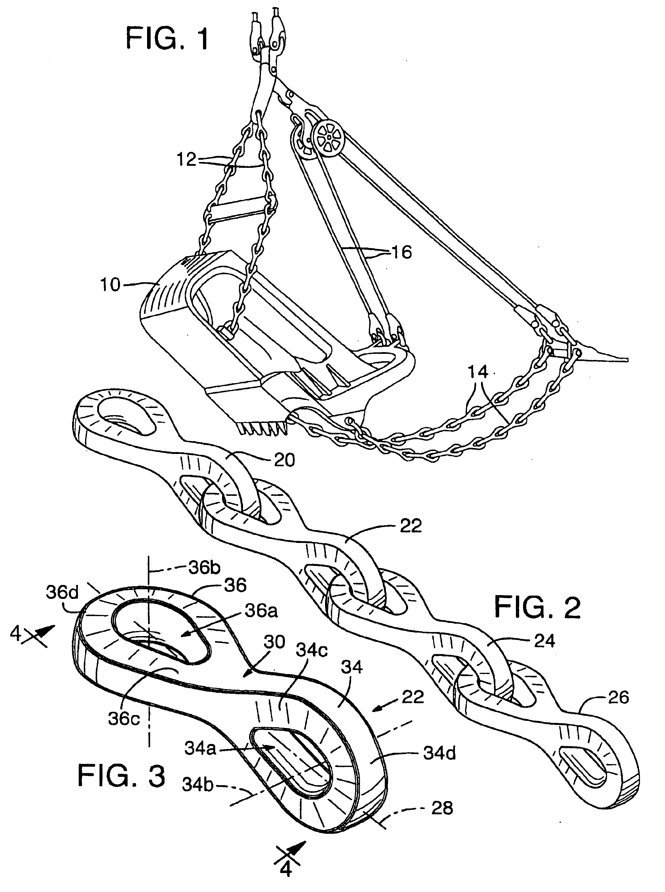
FIG. 2 shows a segment of chain such as could be used for hoist chains 12 or drag chains 14. The chain links in the segment illustrated are constructed according to the present invention.

The segment of chain illustrated includes four substantially similar chain links indicated generally at 20, 22, 24, 26, respectively. The links are pivotally connected in series and all are disposed in substantially the same orientation when the length of chain is held straight as shown in FIG. 2.

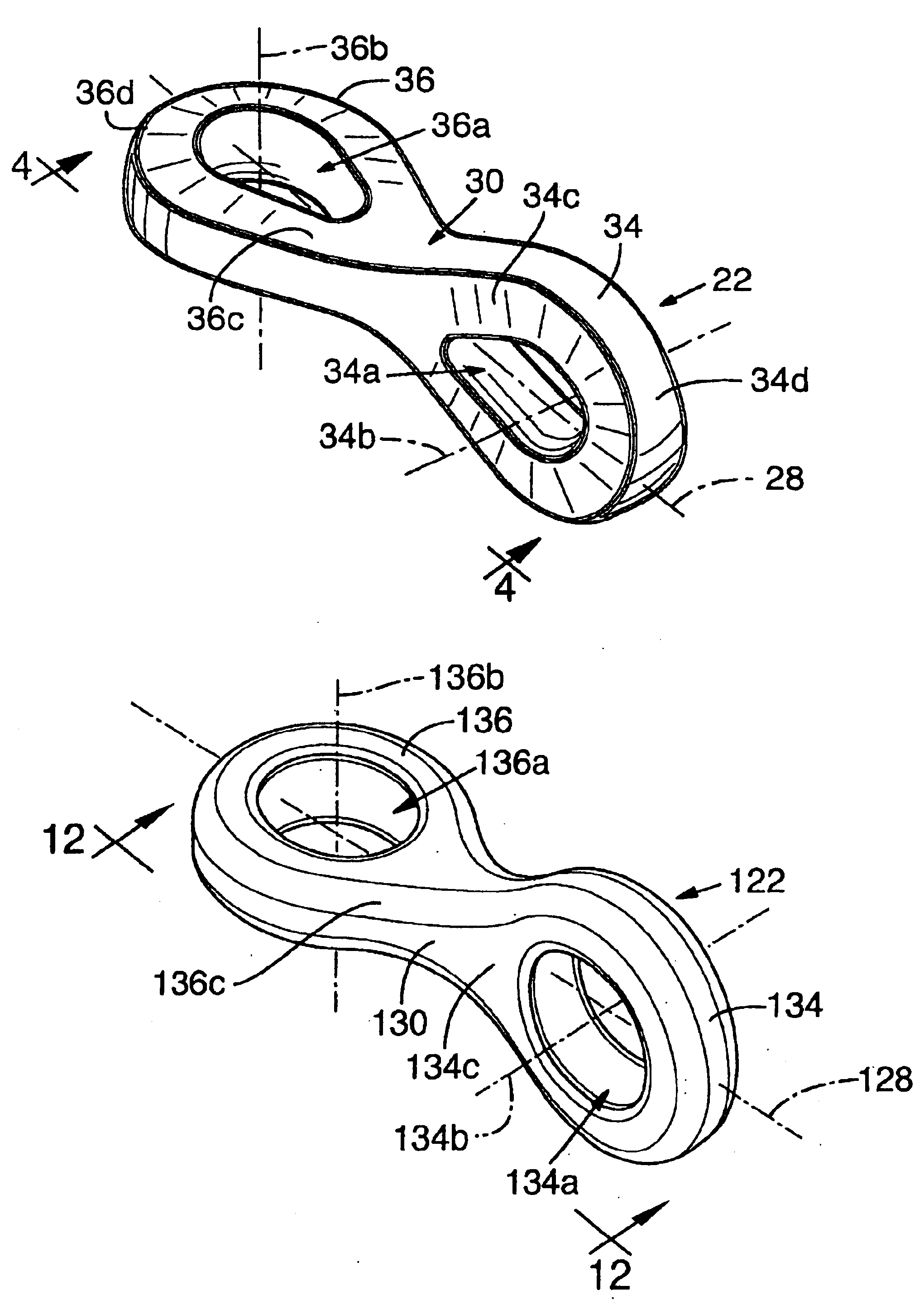
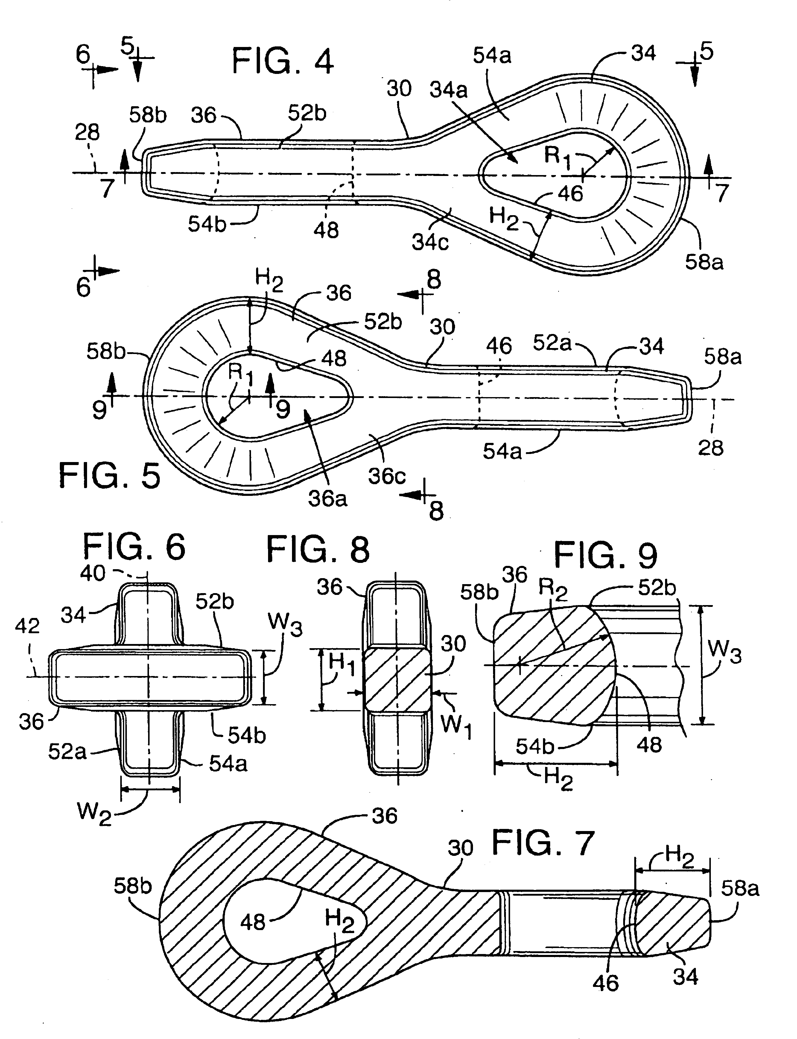
Referring to FIGS. 3-7, a chain link, such as 22, is illustrated in enlarged fashion removed from its interconnection with other chain links. The chain link in the embodiment illustrated is a monolithic cast metal member. It is elongate, having a longitudinal axis indicated generally at 28 in FIG. 3.

The chain link illustrated has a substantially centrally located juncture section 30, a first eye portion 34 integrally connected, or formed, to one end of the juncture section, and a second eye portion 36 integ...

second embodiment

Referring to FIGS. 10-17, another embodiment of the invention is illustrated. The chain link in this chain is similar to that previously described, except for the general configuration of the eye portions at opposite ends of each link. Since the parts of the chain and the chain links are generally similar to those set out in FIGS. 2-9, a similar numbering system will be used, with the addition of a “1” at the beginning of each number. Thus the four substantially similar chain links shown interconnected in FIG. 10 are indicated at 120, 122, 124, 126, respectively. Link 122, illustrated in greater detail in FIGS. 11-17, is constructed in a second embodiment as a monolithic cast metal member. It is elongate, having a longitudinal axis indicated generally at 128 in FIG. 11.

The chain link illustrated in FIGS. 11-17 has a centrally located juncture section 130, a first eye portion 134 integrally connected to one end of the juncture section, and a second eye portion 136 integrally connecte...


PUM


Abstract

A chain link has a substantially centrally located juncture section with a first eye portion integrally connected to one end of the juncture section and a second eye portion integrally connected to the opposite end of the juncture section. The eye portions extend longitudinally outwardly from opposite ends of the juncture section and are disposed at a substantial angle relative to each other at opposite ends of the link. Such link may be connected to contiguous links to form a segment of a chain, with all of the links in a segment of chain thus produced having substantially the same orientation when the chain is held straight.

Description

FIELDThe present invention pertains to chains and chain links in general and more specifically to such chains and chain links adapted for use as hoist chains for heavy equipment.BACKGROUNDMany forms of heavy equipment require chains which have very large load hoisting, or lifting, capabilities. One such field of use for heavy lifting chains is in draglines which are commonly used for removing large volumes of material, such as dirt, loosened ore, etc. Draglines work by dragging a large bucket along the surface to scoop up material and are available in a variety of sizes.Heavy equipment, in the form of draglines are some of the most massive mobile equipment produced, with the largest having capacities in excess of 100 cubic yards per bucket load.The loads on the hoist and drag chains and their links of such equipment are massive. These loads dictate the use of specialized chain links made from high strength alloy steels. In addition, these chains and chain links must be designed to e...

Claims


Application Information

Patent Timeline
Patent Type & Authority Patents(United States)
IPC IPC(8): E02F3/46E02F3/58F16G13/00F16G13/12
CPCF16G13/12E02F3/58
Inventor MOEHNKE, MICHAEL D.DOAN, STEPHEN P.STEWART, RICHARD JOHNCONROY, DAVID GARNET JOHNSIMPSON, MARTIN CHARLESRUSSELL, JAMES ANTHONYLUDE, PETER ALAN
Owner COLUMBIA STEEL CAST PROD LLC
Why Eureka
Try Eureka