Land grid array connector assembly with compact cam driver

a technology of cam driver and connector assembly, which is applied in the direction of coupling contact member, coupling device connection, coupling/disconnecting parts, etc., and can solve the problems of becoming more and more undesirable and even impossibl

Inactive Publication Date: 2005-04-05
HON HAI PRECISION IND CO LTD
View PDF2 Cites 23 Cited by
  • Summary
  • Abstract
  • Description
  • Claims
  • Application Information

AI Technical Summary

Problems solved by technology

In contemporary miniaturized electronic devices such as notebook computers, this is increasingly regarded as efficient use of the valuable “real estate” of the PCB 9, and is becoming more and more undesirable and even not feasible.

Method used


Image

  • Land grid array connector assembly with compact cam driver
  • Land grid array connector assembly with compact cam driver
  • Land grid array connector assembly with compact cam driver

Examples


Embodiment Construction

Reference will now be made to the drawings to describe the present invention in detail.

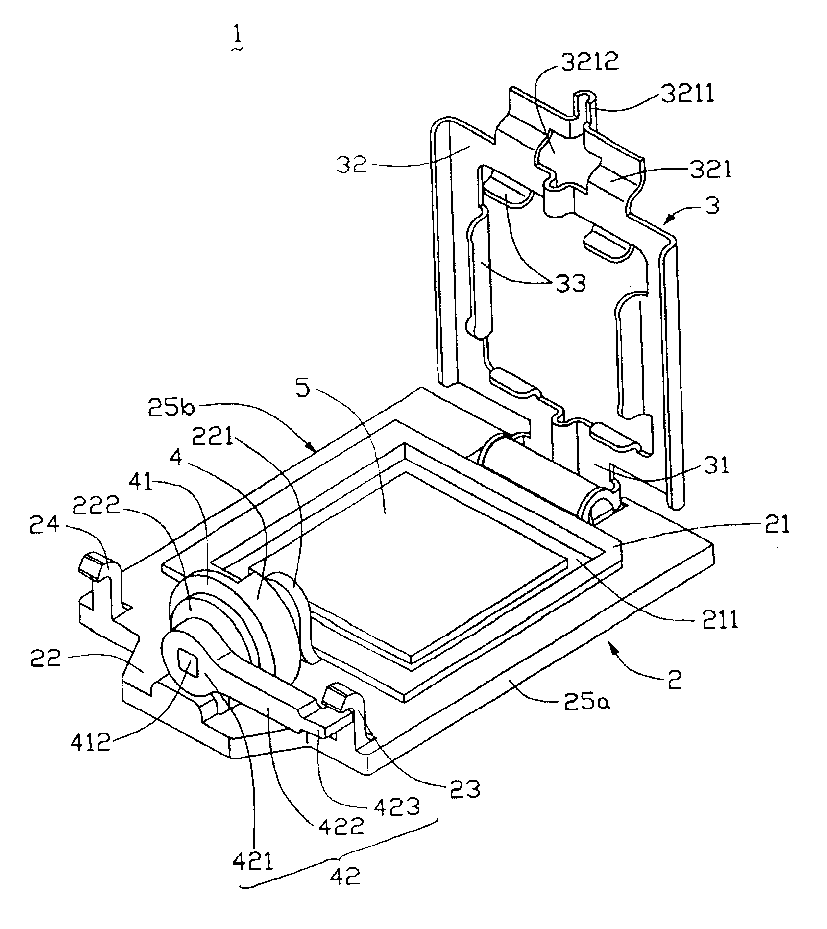
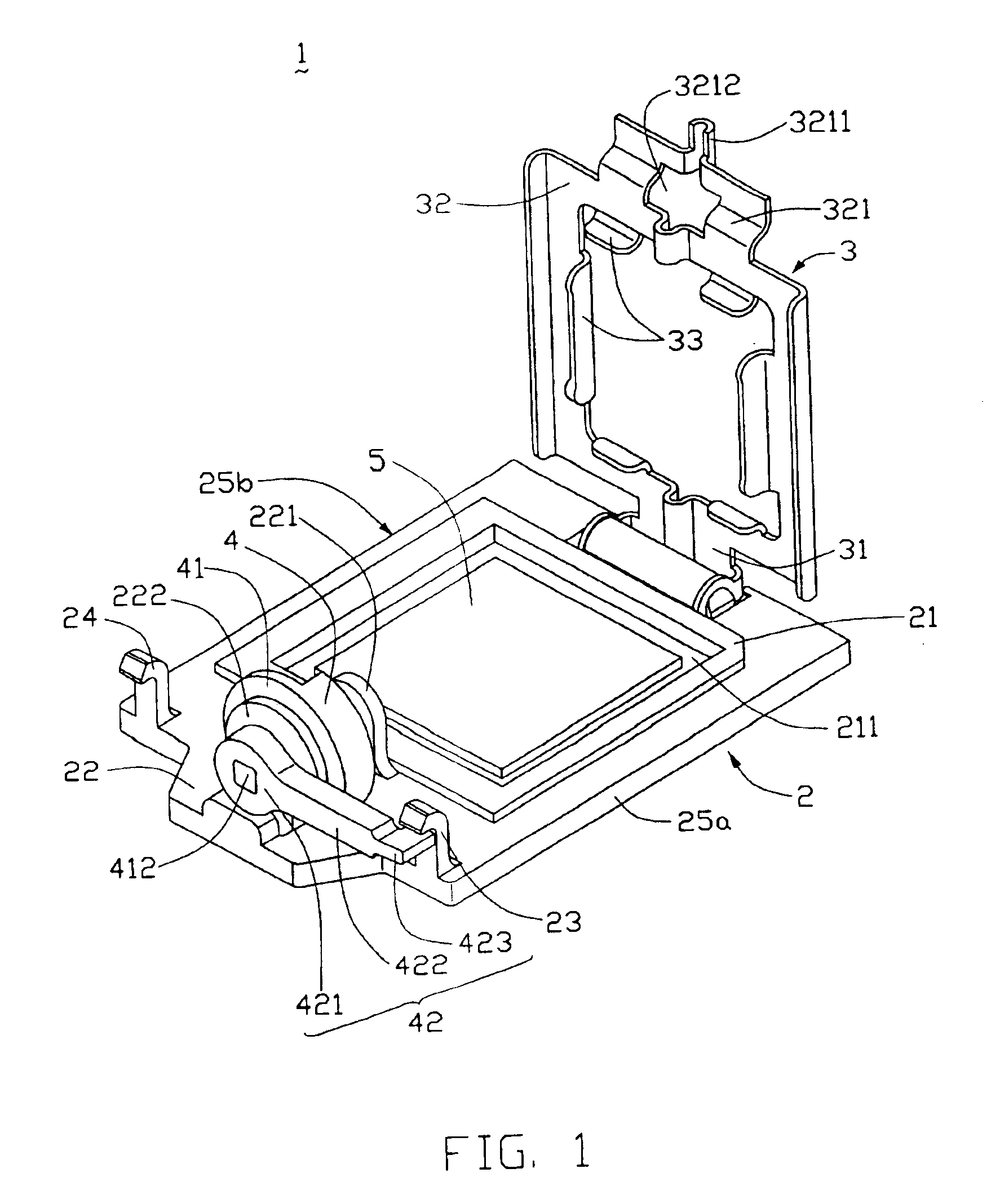
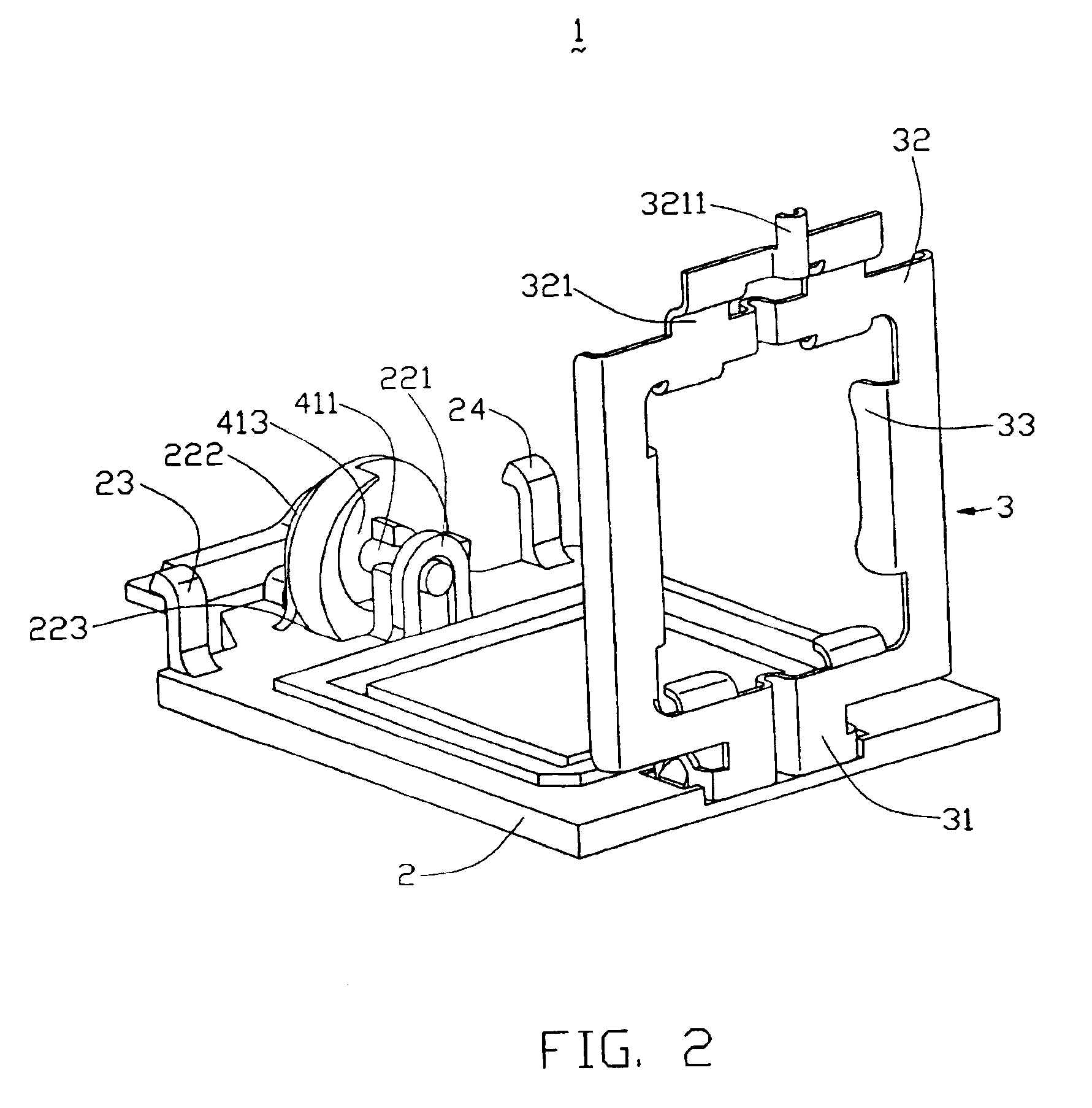
Referring to FIGS. 1 and 2, a land grid array (LGA) connector assembly 1 in accordance with the preferred embodiment of the present invention is for electrically connecting a central processing unit (CPU) (not visible) with a printed circuit board (PCB) (not shown). The LGA connector assembly 1 comprises a socket (not visible), and a fastening device surrounding the socket. The socket has a plurality of LGA contacts provided therein. The fastening device comprises an insulative frame 2 having two opposite lateral edges 25a, 25b interconnected by opposite first and second ends, a metal clip 3 rototably mounted to the first end of the frame 2, and a cam actuator 4 rotatably mounted to the second end of the frame 2.

The frame 2 comprises a low-profile inner peripheral wall 21 on a top thereof The peripheral wall 21 cooperates with a main body of the frame 2 to define a receiving recess 211 therebetwee...


PUM


Abstract

An electrical connector assembly (1) for electrically connecting an electronic package with a circuit substrate. The connector assembly includes a socket and a fastening device surrounding the socket. The fastening device includes a frame (2), a metal clip (3) pivotably mounted to a first end of the frame, and a cam actuator (4) pivitably mounted to a second end of the frame. The clip includes a post (3211) at a free end (32) thereof. The cam actuator includes a cam (41) defining a spiral groove (413) receiving the post and a driver (42) assembled to the cam. When the cam is driven, it drives the post downwardly, and simultaneously the clip moves slightly toward the second end of the frame. In addition, the driver at all times remains substantially within the confines of the main body of the frame.

Description

BACKGROUND OF THE INVENTION1. Field of the InventionThe present invention relates to an electrical connector assembly for electrically connecting an electronic package such as a central processing unit (CPU) with a circuit substrate such as a printed circuit board (PCB), and particularly to a land grid array connector assembly having a fastening device for securing the CPU therein.2. Description of Prior ArtFIG. 6 shows a conventional land grid array (LGA) connector assembly 6 fixed on a printed circuit board (PCB) 9. The (LGA) connector assembly 6 comprises a fastening device 60, and a socket 61 received in the fastening device 60. The fastening device 60 comprises a generally rectangular frame 63, and a lever 62 and a metal clip 64 respectively mounted to opposite ends of the frame 63. The frame 63 defines a pair of locating slots 66 at one end thereof, and a pair of guiding grooves 65 at an opposite end thereof. Each guiding groove 65 is bounded by a first wall 651 and an opposit...

Claims


Application Information

Patent Timeline
Patent Type & Authority Patents(United States)
IPC IPC(8): H01R12/16H01R12/00H01R13/02H01R13/193H01R13/629
CPCH01R12/88H01R13/193H01R13/62905
Inventor MCHUGH, ROBERT G.MA, HAO-YUN
Owner HON HAI PRECISION IND CO LTD
Why Eureka
Try Eureka