Full view sign assembly

Active Publication Date: 2005-04-26
APCO GRAPHICS
View PDF15 Cites 10 Cited by
  • Summary
  • Abstract
  • Description
  • Claims
  • Application Information

AI Technical Summary

Benefits of technology

[0004]Accordingly it is an advantage of the invention claimed herein to provide a sign assembly that need not be removed from a mounted position on a wall or other structure in order to remove and replace the front panel and any sign insert behind the front panel. It is also an advantage of the invention to provide an apparatus having a locking pin for the front panel that may be inserted into and removed from the sign assembly in order to permit removal of the front panel while the assembly is mounted on a wall or other structure. It is a further advantage of the invention to provide a sign assembly having a substantially unobstructed, full view of the front panel of the assembly and of any insert located behind the front panel.
[0005]Additional advantages of this invention will become apparent from an examination of the drawings and the ensuing description.
[0006]As used herein, the term “generally rectangular” refers to the shape of a quadrilateral having at least one pair of substantially parallel sides.
[0007]The invention comprises a sign assembly comprising a support surface including a first side frame portion having a longitudinal first recess along the length thereof, a second side frame portion having a longitudinal second recess along the length thereof, and a back plate disposed between the first side frame portion and the second side frame portion. The first recess and the second recess each have a bottom and a top. The sign assembly also includes a third side frame portion and a fourth side frame portion. The third side frame

Problems solved by technology

Each of these devices, however, suffer from one or more disadvantages.
For example, none of these devices provide a substantially unobstructed, full view front panel that may be removed and replaced while the sign assembly is mounted to a wall or another structure.
Mor

Method used


Image

  • Full view sign assembly
  • Full view sign assembly
  • Full view sign assembly

Examples


Example

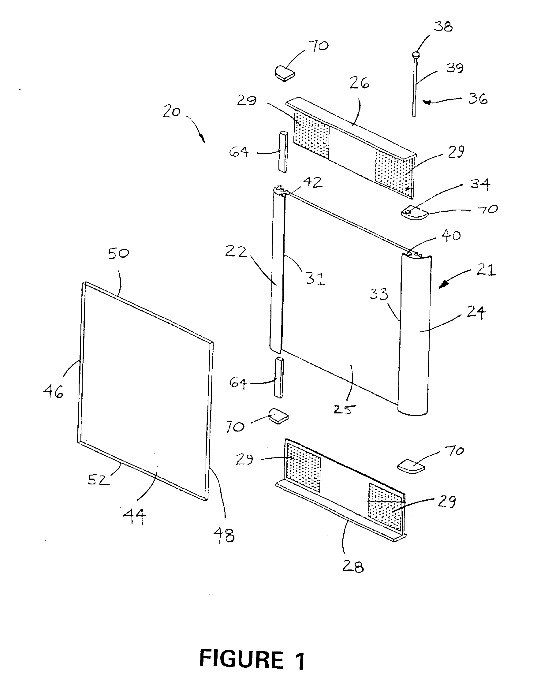
[0026]Referring now to the drawings, FIGS. 1 through 13 illustrate various preferred embodiments of the sign assembly claimed herein. More particularly, FIG. 1 illustrates an exploded perspective view of a preferred embodiment of the sign assembly in accordance with the present invention As shown in FIG. 1, the preferred embodiment of the sign assembly is designated generally by reference numeral 20. Preferred sign assembly 20 includes support surface 21. Support surface 21 includes first side frame portion 22, second side frame portion 24 opposite the first side frame portion, and back plate 25 disposed between the first and second side frame portions. The first side frame portion and the second side frame portion each have a longitudinal recess along the length thereof as more fully discussed below. In a preferred embodiment, the first and second side frame portions are disposed generally parallel to each other. While support surface 21 is shown as being a single extrusion in FIG....


PUM


Abstract

A sign assembly having a support surface including a first side frame portion, a second side frame portion and a back plate. The first and second side frame portions each include a longitudinal recess having a top and a bottom. The sign assembly also includes a third side frame portion, a fourth side frame portion, a front panel and a locking pin. The front panel includes a first side, a second side, a third side and a fourth side. The locking pin is adapted to be inserted into the second recess. The side frame portions, the front panel, and the locking pin are arranged so that when the second side of the front panel and the locking pin are in the second recess, the first side of the front panel will extend into the first recess; and when the locking pin is not in the second recess, the front panel may be moved so that its second side is toward the bottom of the second recess and its first side is out of the first recess so that the front panel may be pivoted about the second recess to remove the front panel from the sign frame.

Description

FIELD OF THE INVENTION[0001]This invention relates generally to sign assemblies having removable front panels. More particularly, the invention relates to an apparatus adapted to provide a substantially unobstructed, full view front panel which may be removed while the sign assembly is mounted to a wall or another structure.BACKGROUND AND DESCRIPTION OF THE PRIOR ART[0002]It is known to provide a sign assembly which includes a front panel that may be removed from the supporting frame of the assembly. Examples of such devices are described by U.S. Pat. No. 4,831,754 of Tallent, U.S. Pat. No. 5,781,980 of Golston, and U.S. Pat. No. 5,832,643 of Delaquila et al. Each of these devices, however, suffer from one or more disadvantages. For example, none of these devices provide a substantially unobstructed, full view front panel that may be removed and replaced while the sign assembly is mounted to a wall or another structure. More particularly, none of these devices includes a locking pin...

Claims


Application Information

Patent Timeline
IPC IPC(8): G09F15/00
CPCG09F15/0012G09F15/00
Inventor COBB, RONBELL, BEN
Owner APCO GRAPHICS
Why Eureka
Try Eureka