Pediatric laryngoscope, and method of use

a laryngoscope and a technology for children, applied in the field of laryngoscopes, can solve the problems of increasing the possibility of damage to teeth, gums, lips, and jaws, and requiring intensive pressure to move anatomical structures, so as to facilitate endotracheal intubation, improve visibility, and optimize laryngeal exposure

Inactive Publication Date: 2019-06-25
DORESWAMY SRINIVASA MURTHY
View PDF5 Cites 0 Cited by
  • Summary
  • Abstract
  • Description
  • Claims
  • Application Information

AI Technical Summary

Benefits of technology

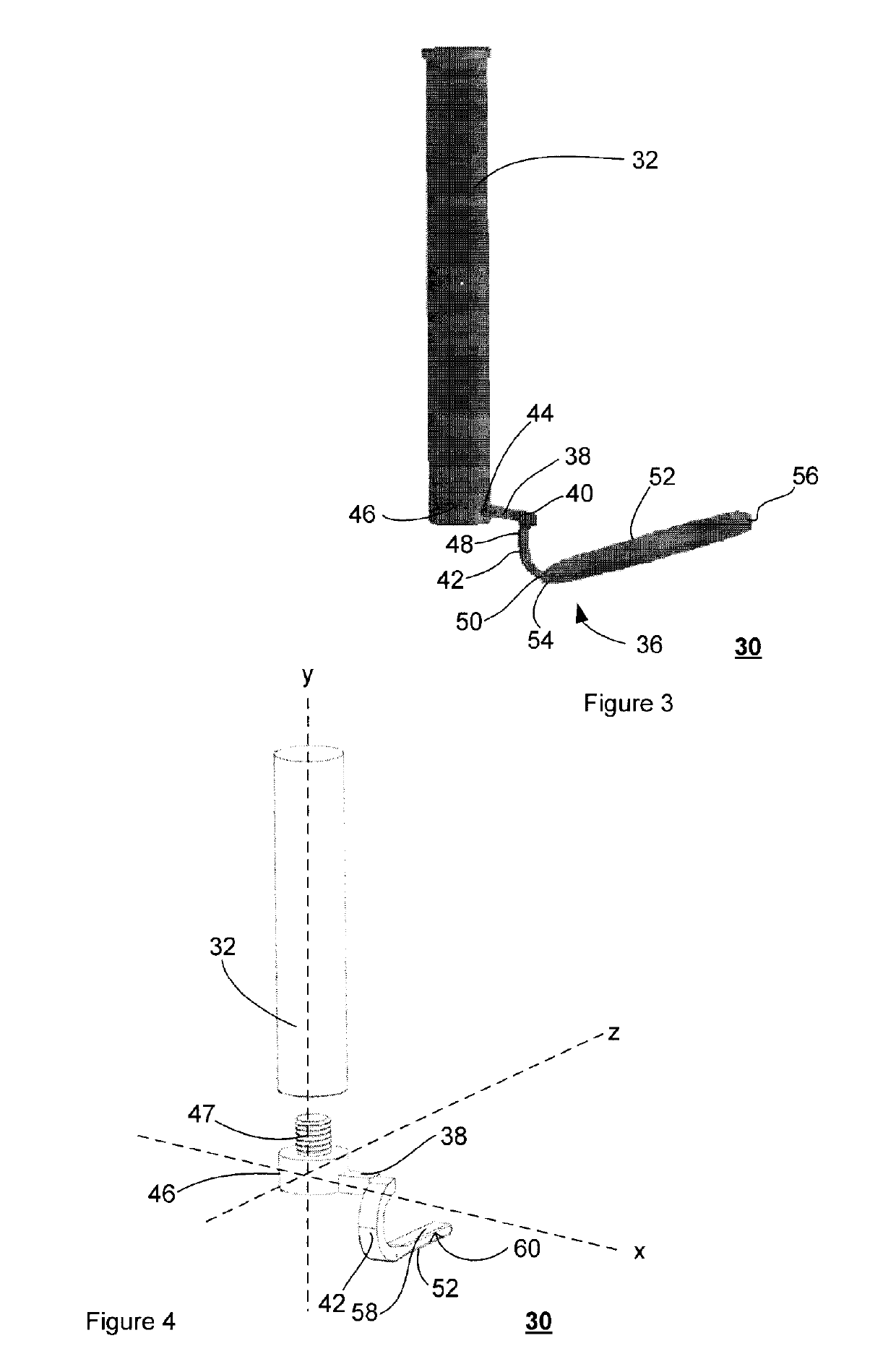
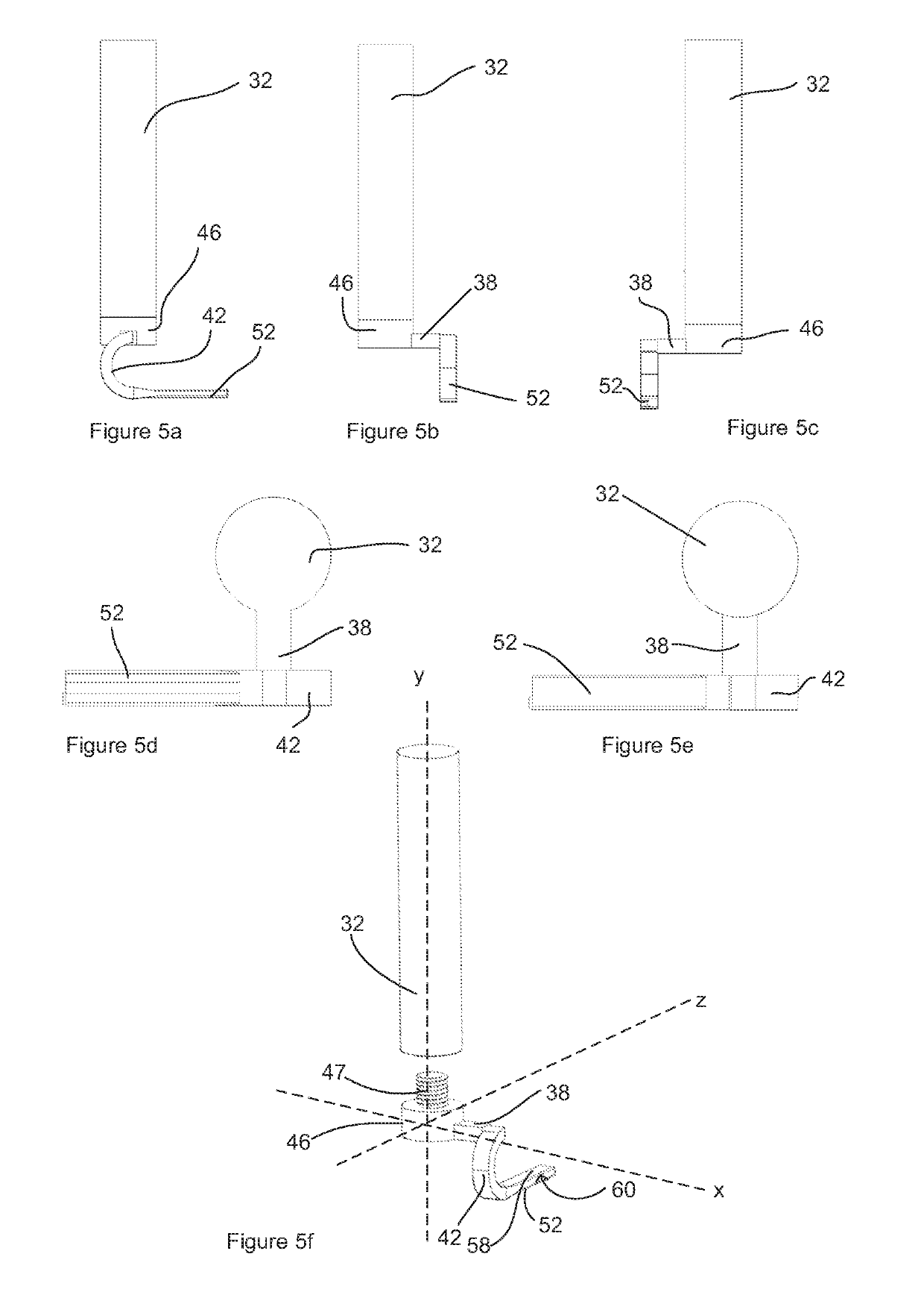
[0010]wherein said offset member is orthogonal to said handle and said blade, and disposes said blade away from said handle to increase visibility within a buccal cavity of a patient by placing said handle away from a line of sight of an operator when blade is placed in the buccal cavity.
[0026]whereby said offset member disposes said blade away from said blade mount to increase visibility within said buccal cavity by placing said handle away from a line of sight when said blade is placed in the buccal cavity to provide a substantially unobstructed view within said buccal cavity for said laryngeal exposure.
[0027]Advantageously, the laryngoscope optimizes laryngeal exposure, and therefore facilitates endotracheal intubation, especially in a neonate, and substantially diminishes the likelihood of trauma to the surrounding oral structures during intubation, thereby enhancing safety. In addition, the laryngoscope is intuitive and therefore can be used easily without additional training.

Problems solved by technology

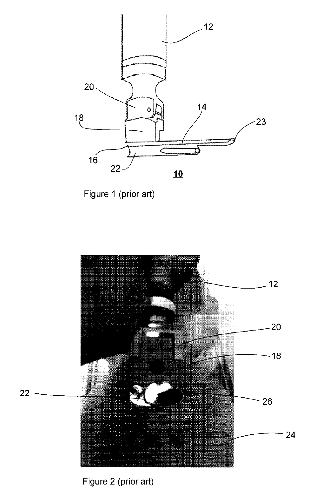
While the market is awash with prior art pediatric laryngoscopes, these laryngoscopes are merely scaled-down versions of adult laryngoscopes, and are therefore not designed specifically for neonatal use.
While these attributes and features are useful or essential in adult laryngoscopes, these features may be non-essential or ill-suited for pediatric applications.
Additionally, the overall structure of the blade 14 often results in the requirement of intensive pressure to move the anatomical structures to expose the larynx.
In exerting the required pressure, the operator is sometimes forced to pry against the patient's upper teeth, thereby increasing the possibility of damage to the teeth, gums, lips, and jaw, which is undesirable, especially in pediatric patients 24.
Generally, use of the prior art laryngoscope requires extensive training, for example, proper positioning of the blade 14 requires a series of manoeuvres of the operator's shoulder, which may place the operator in awkward, and non-ergonomic positions, and may be tiresome in certain challenging emergency cases.

Method used


Image

  • Pediatric laryngoscope, and method of use
  • Pediatric laryngoscope, and method of use
  • Pediatric laryngoscope, and method of use

Examples


Embodiment Construction

[0054]The detailed description of exemplary embodiments of the invention herein makes reference to the accompanying block diagrams and schematic diagrams, which show the exemplary embodiment by way of illustration and its best mode. While these exemplary embodiments are described in sufficient detail to enable those skilled in the art to practice the invention, it should be understood that other embodiments may be realized and that logical and mechanical changes may be made without departing from the spirit and scope of the invention. Thus, the detailed description herein is presented for purposes of illustration only and not of limitation. For example, the steps recited in any of the method or process descriptions may be executed in any order and are not limited to the order presented.

[0055]Moreover, it should be appreciated that the particular implementations shown and described herein are illustrative of the invention and its best mode and are not intended to otherwise limit the ...


PUM


Abstract

A laryngoscope assembly having: a handle; an offset member having a first end coupled to said handle; and a blade coupled to a second of said offset member; and wherein said offset member is orthogonal to said handle and said blade, and disposes said blade away from said handle to increase visibility within a buccal cavity of a patient by placing said handle away from a line of sight of an operator when said blade is placed in said buccal cavity.

Description

FIELD OF THE INVENTION[0001]The present invention relates to endotracheal intubation instruments, more particularly it relates to a laryngoscope.DESCRIPTION OF THE RELATED ART[0002]Laryngoscopes are well known in the art, and are used to visualize the larynx for proper diagnosis of laryngeal disorders, such as, vocal cord paralysis. They are also used to assist with the placement of a tube from a ventilator machine into a patient's trachea to aid with the oxygenation of the patient, a procedure commonly referred to as endotracheal intubation. Oftentimes, endotracheal intubation is performed pre-emptively to avoid serious emergencies in situations which may result in cessation of breathing unexpectedly, such as brain injury, brain infection, sepsis, serious multi-trauma, and metabolic derangement. In such emergency situations, the proper positioning of the laryngoscope and placement of the tube must be performed in a quick and safe manner.[0003]Over the years, it has become common to...

Claims


Application Information

Patent Timeline
Patent Type & Authority Patents(United States)
IPC IPC(8): A61B1/267A61B1/00A61B1/07A61B1/06A61B1/04
CPCA61B1/267A61B1/00124A61B1/04A61B1/2673A61B1/0669A61B1/0676A61B1/07A61B1/0661A61B1/044
Inventor DORESWAMY, SRINIVASA MURTHY
Owner DORESWAMY SRINIVASA MURTHY
Why Eureka
Try Eureka