Outdoor window

a technology for outdoor windows and doors, applied in the field of windows, can solve the problems of large amount of rainwater flowing onto the flat surface of the sliding sash, high risk, etc., and achieve the effects of ensuring the strength and rigidity of the sill, superior drainage, and superior air tightness and water tightness

Inactive Publication Date: 2005-04-26
TATEYAMA ALUMINUM IND
View PDF20 Cites 42 Cited by
  • Summary
  • Abstract
  • Description
  • Claims
  • Application Information

AI Technical Summary

Benefits of technology

[0010]The present invention may provide an outdoor window with a flat sill, which is disposed in a doorway of a building opening which separates an indoor side and an outdoor side. The outdoor window is of a barrier free type in which the top surface of a window sill is made approximately flat in such a way that projecting rails are eliminated from the top surface of the window sill and steps which would have been disposed in the direction in which a person goes in and out are eliminated. The outdoor window is superior in the drainage of rainwater or the like accompanied by wind pressure and is high in watertightness against indoor water leakage. More particularly, the invention aims to provide a structure which is effective in improving the drainage of rainwater or the like while ensuring the strength and rigidity of the sill in the case where a linear drain groove is provided on the above-described flat surface.
[0023]In addition, there is provided a sealing member which separates an outdoor (exterior) side and an indoor (interior) side, according to the opening / closing mechanism of a window such as a double-sliding window or a single-sliding window, and since the drain groove and the drain port are provided to correspond to this sealing portion, the flow of outside air and rainwater can be stopped at the sealing portion, and rainwater can be made to flow downwardly. Accordingly, it is possible to achieve superior airtightness and watertightness while ensuring the strength and the rigidity of the sill.

Problems solved by technology

However, in the case where a window which is installed in an outdoor opening of a building is formed as a merely flat structure in which projecting rails are eliminated from the top surface of an existing projecting-rail type of sill (refer to FIG. 20) to simply eliminate steps which would have been disposed in the direction in which a person goes in or out, there is a high risk that a large amount of rainwater which blows on a sliding sash or the like under a large wind pressure during a rain storm flows onto that flat surface and rainwater enters an indoor side together with a flow of wind.
On the other hand, in the case where a groove is provided on the flat surface of a sill and a large drain space is provided below the groove, it is impossible to ensure strength and rigidity enough to support the weight of a door or the weight of a person who goes in and out.
Therefore, a barrier free outdoor opening has been considered to be difficult to realize.
As a result, the manipulating force required to move a sliding sash is increased by the resistance of the tight materials provided on the opposite sides, and in addition, since the tight materials provided on the opposite sides of the projecting portion hinder outside air from entering a groove in the sill, the difference between the pressure of outside air and the pressure of the groove portion of the sill becomes large, so that it is difficult to realize stable sealing along the entire length of the projecting portion.
This leads to the technical problem that owing to such pressure difference, rainwater concentratively flows through a weakly sealed portion and enters an indoor side.
This fact leads to the technical problem that sliding manipulability is inferior and rainwater stored in the bottom guide enters an indoor side owing to a capillary phenomenon and the pressure difference between outside air and the indoor side.
In addition, since a drain passage is only disclosed as a mere idea, it is impossible to obtain strength enough to support the weight of a door and the weight of a person who goes in and out.

Method used


Image

  • Outdoor window
  • Outdoor window
  • Outdoor window

Examples


Embodiment Construction

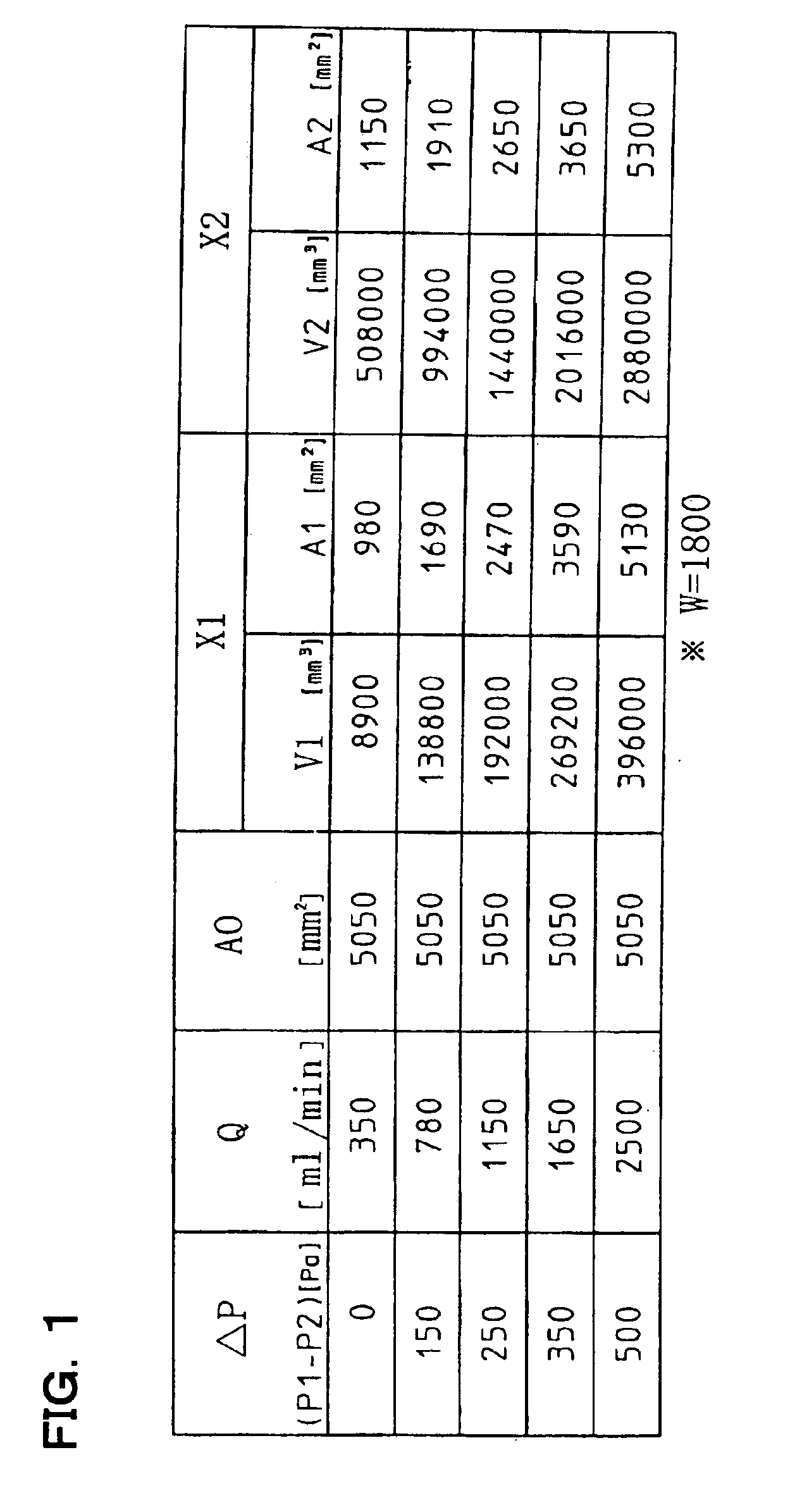
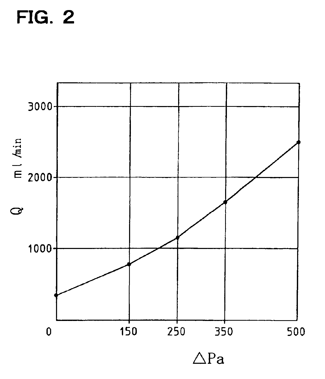
[0044]The functions of a window in accordance with one embodiment of the invention with respect to airtightness, watertightness and drainage will be described below in detail on the basis of schematic views of the window and the result of experimentation.

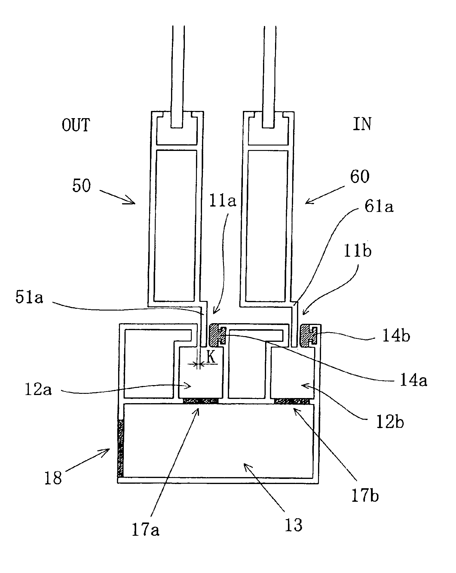
[0045]The schematic view shown in FIG. 5 shows the state in which neither wind nor rain is loaded onto sliding sashes.

[0046]In the shown structure, drain grooves 11a and 11b are provided in a sill whose top surface is formed as a flat surface, and vertically downwardly extended portions 51a and 61a which are respectively provided on the bottom rails of an outer sliding sash 50 and an inner sliding sash 60 are inserted in the respective drain grooves 11a and 11b and are slidable in the opening / closing directions of the sliding sashes. Tight materials 14a and 14b are disposed on the indoor sides of the respective vertically downwardly extended portions.

[0047]Accordingly, the vertically downwardly extended portions provided on the resp...


PUM


Abstract

The outdoor window includes a sealing member provided between each sliding sash and sill so that a sealing portion is pressed when a wind pressure is applied to the sliding sashes from the outdoor side, drain grooves provided on a top surface of the sill, water collecting grooves having a width wider than the width of the drain grooves and being provided immediately below the drain groove, drain ports provided at a bottom of the water collecting grooves; a guiding hollow portion provides immediately below the drain ports for guiding rainwater outdoors, and an outdoor drain port provided at an outdoor side of the guiding hollow portion. The water collecting grooves and the guiding hollow portion communicate with outside air.

Description

[0001]This application is a continuation of International Application No. PCT / JP01 / 10411, having an international filing date of Nov. 28, 2001, which designated the United States, the entirety of which is incorporated herein by reference. This application also claims the benefit of Japanese Patent Application No. 2000-366429 filed on Dec. 1, 2000, and Japanese Patent Application No. 2001-140780 filed on May 10, 2001, and are hereby incorporated by reference in their entirety.BACKGROUND OF THE INVENTION[0002]The present invention relates to a window which is installed in an outdoor opening of a building, and more particularly, to an outdoor window having an approximately flat top surface on a sill. This window is superior in drainage from the flat top surface and is superior in airtightness and watertightness on an indoor side even during a rain storm when the top surface on the sill is formed to be flat.[0003]A barrier free structure in which steps are eliminated from the doorways o...

Claims


Application Information

Patent Timeline
Patent Type & Authority Patents(United States)
IPC IPC(8): E06B3/32E06B7/14E06B3/46
CPCE06B7/14E06B3/4609E06B7/22
Inventor FUKURO, TOSHIOUENO, HIDENORIYASHIKI, RYOU
Owner TATEYAMA ALUMINUM IND
Why Eureka
Try Eureka