Progressive addition lenses
a technology of progressive addition and lens, applied in the field of multi-focal ophthalmic lenses, can solve the problems of reduced maximum, localized unwanted astigmatism that may be realized by this design, and unwanted astigmatism or astigmatism introduced or caused by one or more of the lens' surfaces
- Summary
- Abstract
- Description
- Claims
- Application Information
AI Technical Summary
Problems solved by technology
Method used
Image
Examples
example 1
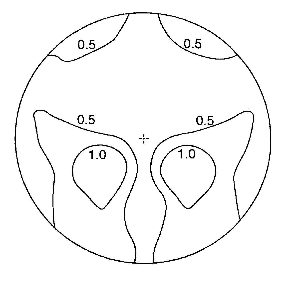
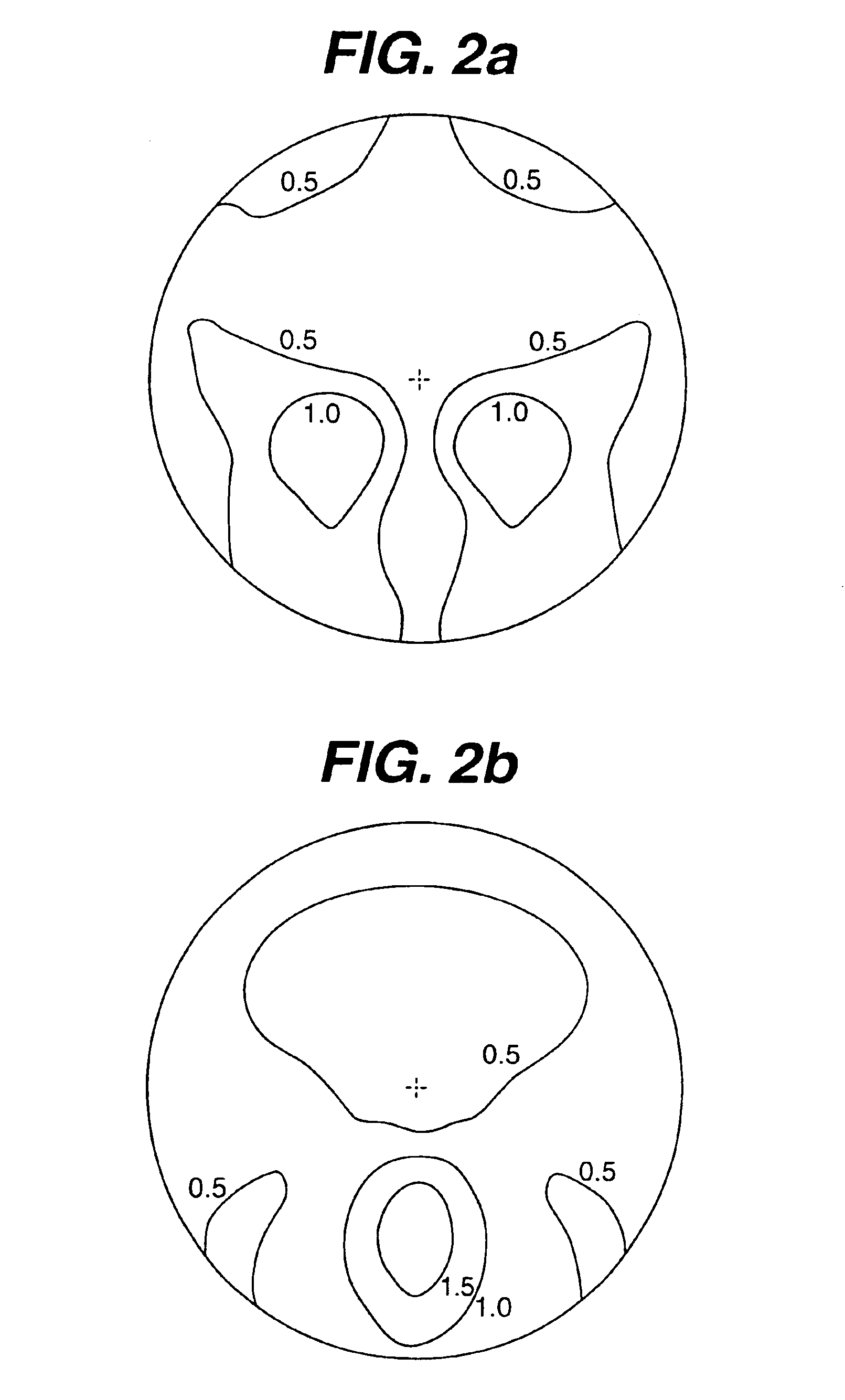
[0056]A soft design, convex progressive addition surface was produced as a sag table wherein Z1 denoted the sag value departure from a base curvature of 5.23 diopters for the distance zone. In FIGS. 2a and 2b are depicted the cylinder and power contours for this surface. The add power was 1.79 diopters with a channel length of 13.3 mm and maximum, localized, unwanted astigmatism of 1.45 diopters at x=−8 mm and y=−8 mm. The prism reference point used was x=0 and y=0 and the refractive index (“RI”) was 1.56.
[0057]A hard design regressive surface design was produced for a convex surface as a sag table wherein Z2 denoted the sag value departure from a base curvature of 5.22 diopters for the distance zone. In FIGS. 3a and 3b are depicted the cylinder and power contours for this surface. The add power was −0.53 diopter, the channel length was 10.2 mm and the maximum, localized unwanted astigmatism was 0.71 diopters at x=−10 mm and y=−10 mm. The prism reference point used was x=0 and y=0 a...
example 2
[0059]A concave progressive addition surface was designed using a material refractive index of 1.573, a base curvature of 5.36 diopters and an add power of 0.75 diopters. FIG. 5 depicts the cylinder contours of this surface. The maximum, localized astigmatism was 0.66 diopters at x=−16 mm and y=−9 mm. The prism reference point used was at x=0 and y=0.
[0060]This concave surface was combined with the convex composite surface from Example 1 to form a lens with a distance power of 0.08 diopters and an add power of 2.00 diopters. In the Table is listed the key optical parameters of this lens (Example 2), and in FIGS. 6a and 6b is depicted the cylinder and power contours. The maximum astigmatism is 1.36 diopters, significantly lower than prior art lenses shown in the Table 1 as Varilux COMFORT® (Prior Art Lens 1 and FIGS. 7a and 7b. The normalized lens distortion of the lens is calculated to be 287, significantly less than the prior art lenses of Table 3. Additionally, none of the other o...
example 3
[0061]In order to demonstrate the capability of the design approach of the invention to optimize specific optical parameters, specifically the reading power width, a concave progressive addition surface was designed using a material RI of 1.573, a base curvature of 5.4 diopters and an add power of 0.75 diopters. In FIG. 8 is depicted the cylinder contour of this surface. The maximum, localized astigmatism was 0.51 diopters at x=−15 mm and y=−9 mm. The prism reference point used was at x=0 and y=0.
[0062]This concave surface was combined with the convex composite surface from Example 1 to form a lens with a distance power of 0.05 diopters and an add power of 2.00 diopters. In the Table is listed the key optical parameters of this lens (Example 3), and in FIGS. 9a and 9b is shown the cylinder and power contours. The maximum astigmatism is 1.37 diopters, significantly lower than the prior art lens shown in Table 1 as Varilux COMFORT®—(Prior Art Lens 1 and FIGS. 7a and 7b. The normalized...
PUM
 Abstract
Description
Claims
Application Information
 - R&D
- Intellectual Property
- Life Sciences
- Materials
- Tech Scout
- Unparalleled Data Quality
- Higher Quality Content
- 60% Fewer Hallucinations
Browse by: Latest US Patents, China's latest patents, Technical Efficacy Thesaurus, Application Domain, Technology Topic, Popular Technical Reports.
© 2025 PatSnap. All rights reserved.Legal|Privacy policy|Modern Slavery Act Transparency Statement|Sitemap|About US| Contact US: help@patsnap.com


