Fluid circulation path for motor pump

a technology of motor pumps and circulation paths, applied in the field of fluid pumps, can solve problems such as unbalanced thrust against the pumping elements, increase wear and tear, and create potential leakage paths, and achieve the effect of increasing the fluid pressur

Inactive Publication Date: 2005-04-26
STANDEX INT CORP
View PDF37 Cites 50 Cited by
  • Summary
  • Abstract
  • Description
  • Claims
  • Application Information

AI Technical Summary

Problems solved by technology

Motors employed in such pumps are often run “wet” in that the pumped fluid is circulated through the motor with a portion of the fluid returned to the pump head inlet where the fluid is inefficiently re-pumped.
Additionally, the pressurized fluid often is directed out of the pump head in a way that creates unbalanced thrust against the pumping elements.
Such unbalanced thrusting can increase wear and tear and open up gaps between the pump head components, thereby creating potential leak paths.

Method used


Image

  • Fluid circulation path for motor pump
  • Fluid circulation path for motor pump
  • Fluid circulation path for motor pump

Examples


Embodiment Construction

)

[0023]Preferred embodiments of the present invention will now be described with reference to the accompanying drawings, wherein like reference characters designate like or similar parts throughout. The terminology used herein is intended to be interpreted in its broadest reasonable manner, even though it is being utilized in conjunction with a detailed description of certain specific preferred embodiments of the present invention. This is further emphasized below with respect to some particular terms used herein. Any terminology intended to be interpreted by the reader in any restricted manner will be overtly and specifically defined as such in this specification.

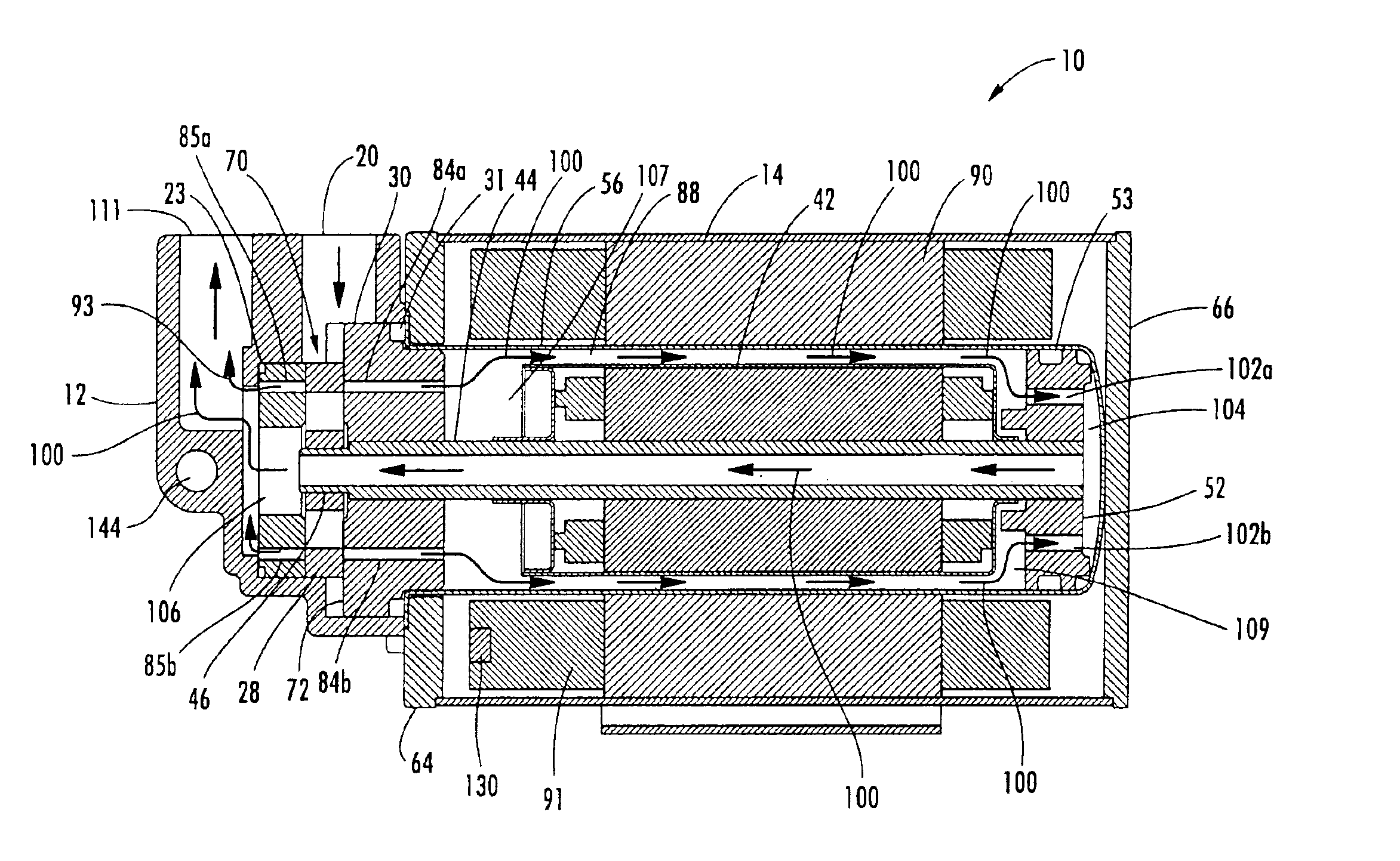
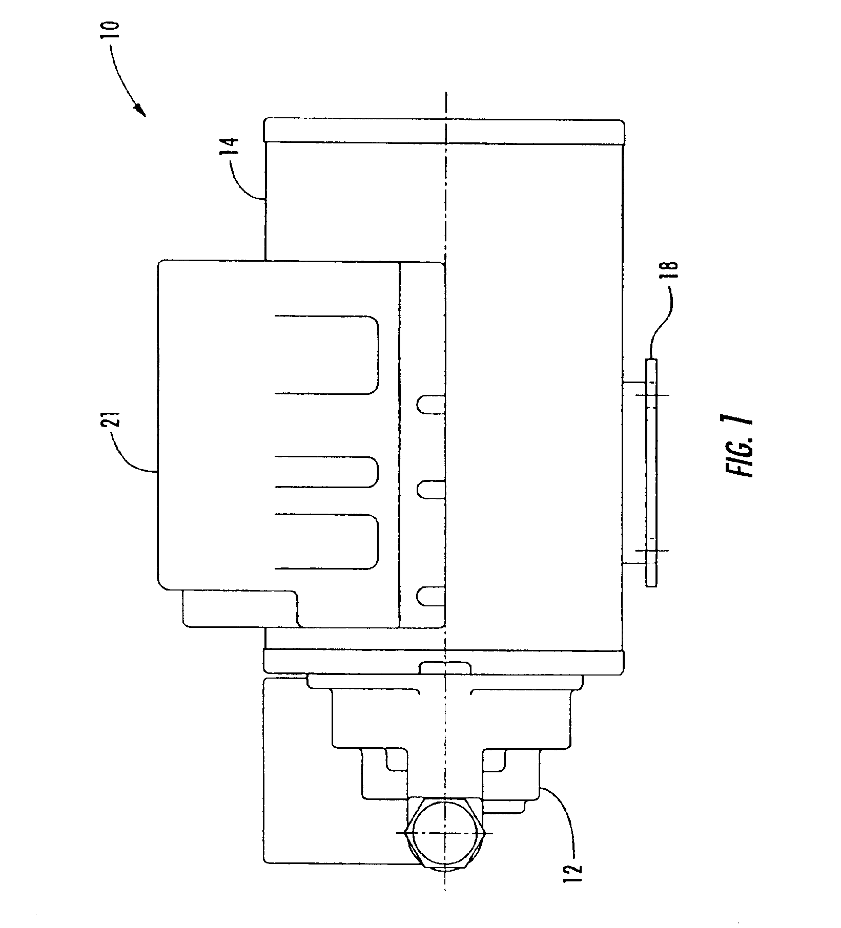
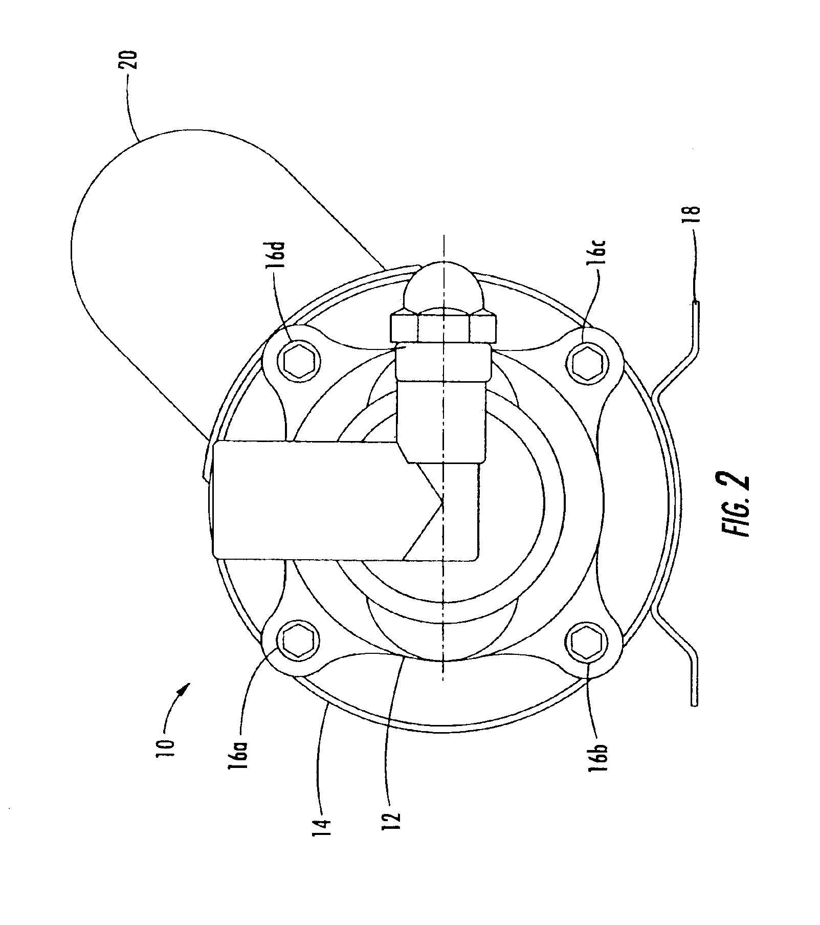
[0024]FIGS. 1 and 2 illustrate, respectively, side and end views of a canned motor pump 10 according to a preferred embodiment of the invention. The pump 10 includes a pump head housing 12 which houses internal components of the pump attached to a motor housing 14 for housing electric motor components. The pump head housin...


PUM


Abstract

A fluid pump includes a pump head having an inlet for receiving fluid at a first pressure and an outlet for outputting fluid at a second pressure greater than the first pressure. Pressurized fluid is directed through a first passage to the outlet without the pressurized fluid leaving the pump head prior to reaching the outlet. A second passage directs pressurized fluid to a fluid circulation path which is at least partially external to the pump head with the fluid circulation path terminating adjacent the outlet. Pressurized fluid passing through the first and second passages is directed to the outlet without being re-pressurized by the pump head. The first and second passages are in opposed relation to one another to provide balancing of thrust produced by the flow of pressurized fluid through the passages. An electric motor drives the pump head. The fluid circulation path may include portions of the electric motor.

Description

[0001]This nonprovisional application claims priority to provisional application Ser. No. 60 / 360,693 filed Feb. 28, 2002, and entitled “Canned Motor Pump.”FIELD OF THE INVENTION[0002]The present invention relates generally to fluid pumps. More particularly, the present invention relates to a motor pump which pressurizes a fluid, directs the fluid out of the pump head in a balanced fashion, and then circulates the pressurized fluid through the pump and its motor without having to re-pump the circulated fluid.BACKGROUND OF THE INVENTION[0003]Fluid pumps with integral motors, such as so-called “canned” pumps, are generally employed in a variety of applications. For example, fluid motor pumps can be used to move fluids such as chemicals and oils. Motors employed in such pumps are often run “wet” in that the pumped fluid is circulated through the motor with a portion of the fluid returned to the pump head inlet where the fluid is inefficiently re-pumped. Additionally, the pressurized flu...

Claims


Application Information

Patent Timeline
Patent Type & Authority Patents(United States)
IPC IPC(8): F04C11/00F04C15/00F04C29/04F04C23/00F04D13/06F04D29/08F04D29/58F04D29/10H02K5/12H02K5/128F04C2/00F04C2/344F04C29/02F04C14/06F04C14/26F04C14/28
CPCF04D13/064F04C11/008F04C14/06F04C14/26F04C14/28F04C15/0042F04C15/0096F04C23/008F04C29/045F04D29/106F04D29/588H02K5/128F04D13/0633F04B2201/0801F04C2/3446F04C15/008F04C29/023F04C2240/40F04C2270/18F04C2270/19F04B2203/0205
Inventor KIMBERLIN, ROBERT R.HARVEY, III, ROBERT E.LARSON, WILLIAM M.RAWNSLEY, JR., WILLIAM C.
Owner STANDEX INT CORP
Why Eureka
Try Eureka