
Method and apparatus for storage and deployment of folded panel structures

a technology for folding panels and storage, applied in the field of deployment, can solve the problems of complex electromechanical devices of booms, the space and weight requirements of booms, and the risk of extreme stress and vibration of deployment booms

Inactive Publication Date: 2005-05-03
RAYTHEON CO
View PDF5 Cites 21 Cited by
  • Summary
  • Abstract
  • Description
  • Claims
  • Application Information

AI Technical Summary

Benefits of technology

The patent text describes a solution for creating a deployable structure that can be easily moved and set up. The structure includes a support and a variety of structural elements, such as torsion springs and remote mechanical de-latching mechanisms. The structural elements are mechanically attached to the support and can be remotely activated or de-latched. The method for constructing and storing the structure involves determining the size of the deployed structure, forming a continuous perimeter shape with the structural element, and folding the perimeter shape into uniform sections for easy storage. The invention also includes an improved self-erecting turnstile antenna system with a supporting device and multiple antenna elements connected to the supporting device. The system includes a latching mechanism assembly that maintains the antenna elements in a non-deployed state until they are remotely activated or de-latched.

Problems solved by technology

It will be appreciated that such deployment booms are complicated electromechanical devices subject to mechanical or electrical malfunction.
It will also be recognized that a disadvantage of such booms is their space and weight requirements, a major consideration in the case of spacecraft and / or portable devices.
For example, during the launch of a spacecraft, the deployment boom may be subjected to extreme stresses and vibrations.
Likewise, a portable device containing such a deployment boom may be subjected to harsh and damaging handling.

Method used


Image

  • Method and apparatus for storage and deployment of folded panel structures
  • Method and apparatus for storage and deployment of folded panel structures
  • Method and apparatus for storage and deployment of folded panel structures

Examples


Embodiment Construction

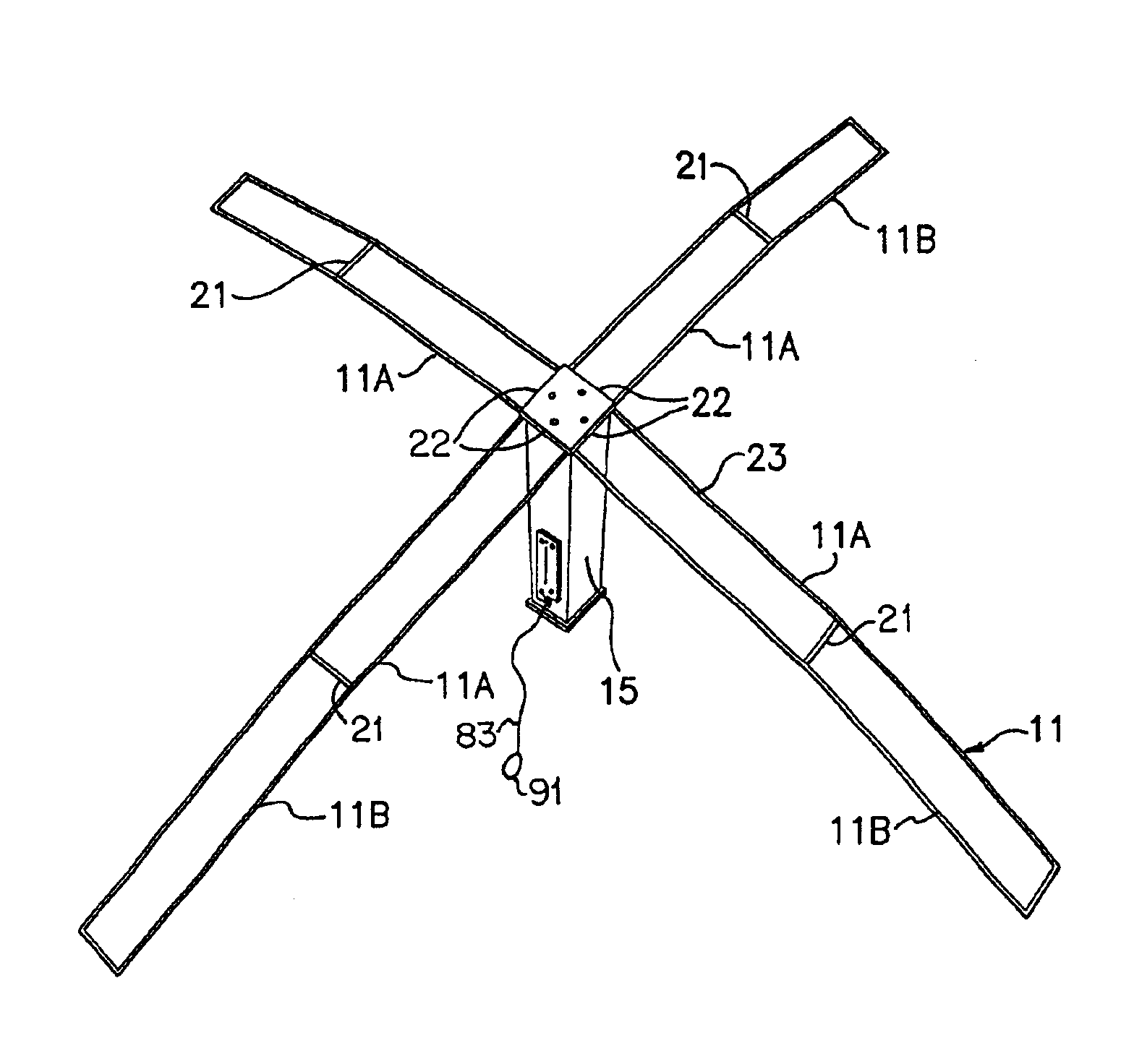
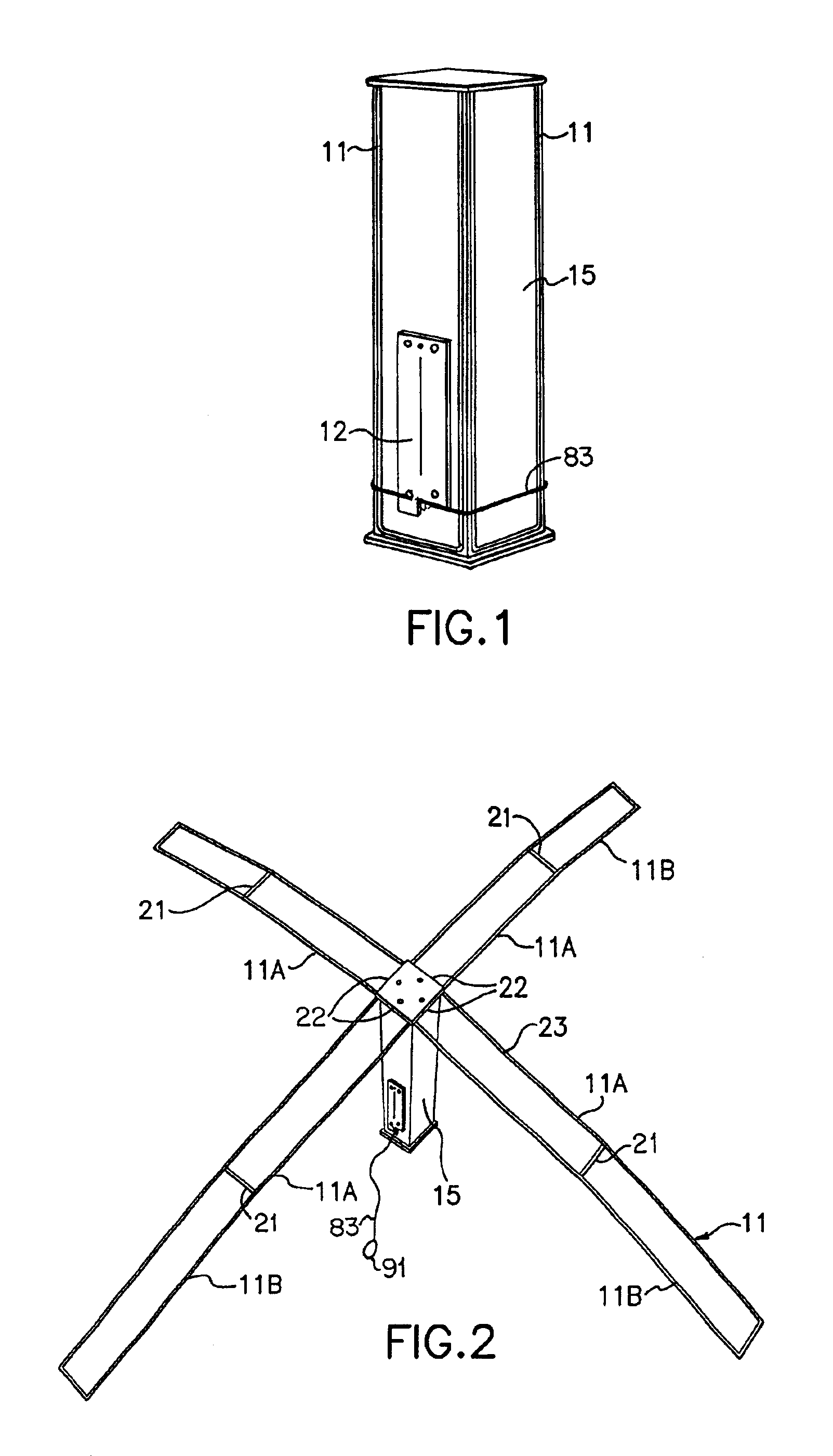
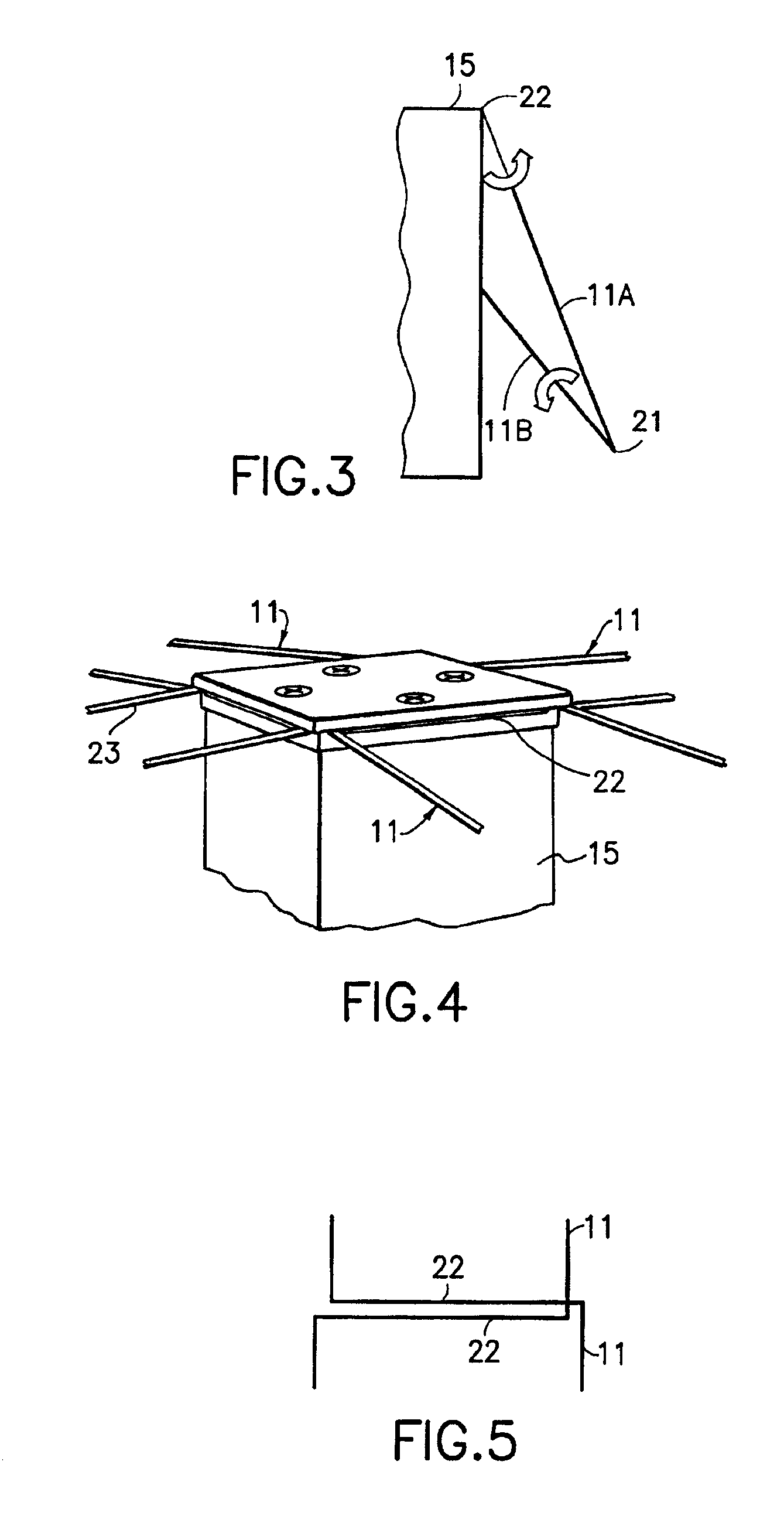
[0007]The foregoing and other problems are overcome, and other advantages are realized, in accordance with the presently preferred embodiments of these teachings. As will be described below, important aspects of the invention reside in the construction and combination of structural elements; structural elements such as torsion springs and remote mechanical de-latching mechanisms.

[0008]In accordance with one embodiment of the invention a deployable structure having a support and at least one structural element is provided. The structural element is mechanically attached to the support. A latching mechanism assembly is adapted to contain the structural element in a non-deployed state until it is remotely activated or de-latched.

[0009]In accordance with another embodiment the invention includes a method for constructing and storing a deployable structure. The method includes the steps of determining a deployed rectangular structure size; forming a perimeter shape of the deployed rectan...


PUM


Abstract

A deployable structure comprising a support and at least one structural element is provided. The structural element is mechanically attached to the support. The latching mechanism assembly is adapted to containing the structural element in a non-deployed state until it is remotely activated or de-latched.

Description

RIGHTS OF THE GOVERNMENT[0001]This invention was made with U.S. Government support.BACKGROUND[0002]1. Field of Use[0003]These teachings relate generally to deployable structures in general and, more particularly, to the storage and remote deployment of folded panel structures.[0004]2. Description of Prior Art[0005]Deployable panels, such as solar arrays with folding solar panels, are known in the art. A typical solar array of this type has a support, such as the body of the spacecraft, that mounts a remote controlled deployment boom that may be extended outwardly from one side of the support. Attached to the deployment boom is a folding solar panel composed of a number of panel sections hinged edge-to-edge along hinge lines extending normal to an extension axis of the boom. The two end panel sections are attached, respectively, to the support and to a cross-member at the outer end of the boom. In the stowed configuration of the solar array, the deployment boom is retracted to locate...

Claims


Application Information

Patent Timeline
Patent Type & Authority Patents(United States)
IPC IPC(8): H01Q15/14H01Q15/20B64G1/22B64G1/44
CPCB64G1/222H02S30/20B64G1/44Y02E10/50B64G1/2228B64G1/2224
Inventor GRAHAM, JASON S.MCCLURE, DAVID L.
Owner RAYTHEON CO
Learn More