Multi-sequenced contacts from single lead frame

a single lead frame and contact technology, applied in the direction of coupling device details, coupling device connections, coupling protective earth/shielding arrangements, etc., can solve the problem of high production cos

Inactive Publication Date: 2005-05-10
TYCO ELECTRONICS LOGISTICS AG (CH)
View PDF14 Cites 122 Cited by
  • Summary
  • Abstract
  • Description
  • Claims
  • Application Information

AI Technical Summary

Problems solved by technology

Additionally, twenty-seven lead frames require additional stampi...

Method used


Image

  • Multi-sequenced contacts from single lead frame
  • Multi-sequenced contacts from single lead frame
  • Multi-sequenced contacts from single lead frame

Examples


Embodiment Construction

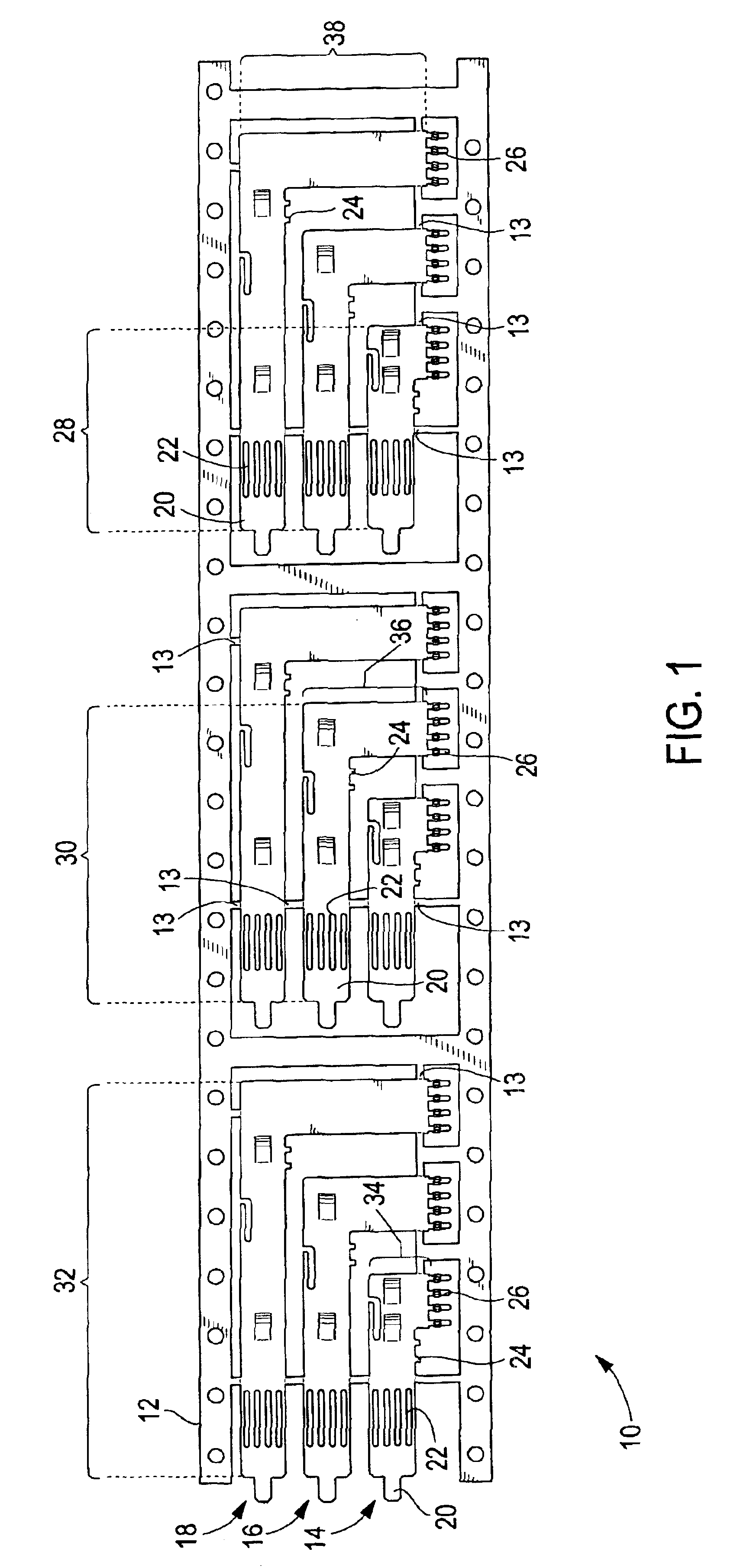
[0024]FIG. 1 illustrates a lead frame strip 10 attached to multiple plug lead frame elements 14, 16 and 18, formed in accordance with an embodiment of the present invention. A set of plug lead frame elements includes the plug lead frame elements 14, 16 and 18. During the stamping or manufacturing process, the plug lead frame elements 14, 16 and 18 are formed integrally with a carrier strip 12 of the lead frame strip 10. Identical sets of plug lead frame elements 14, 16 and 18 are formed. The lead frame strip 10 includes the carrier strip 12 connected to plug lead frame elements 14, 16, and 18, respectively, at breaking points 13. The breaking points 13 may be perforated, or otherwise weakened, to facilitate removal of the plug lead frame elements 14, 16 and 18 from the carrier strip 12.

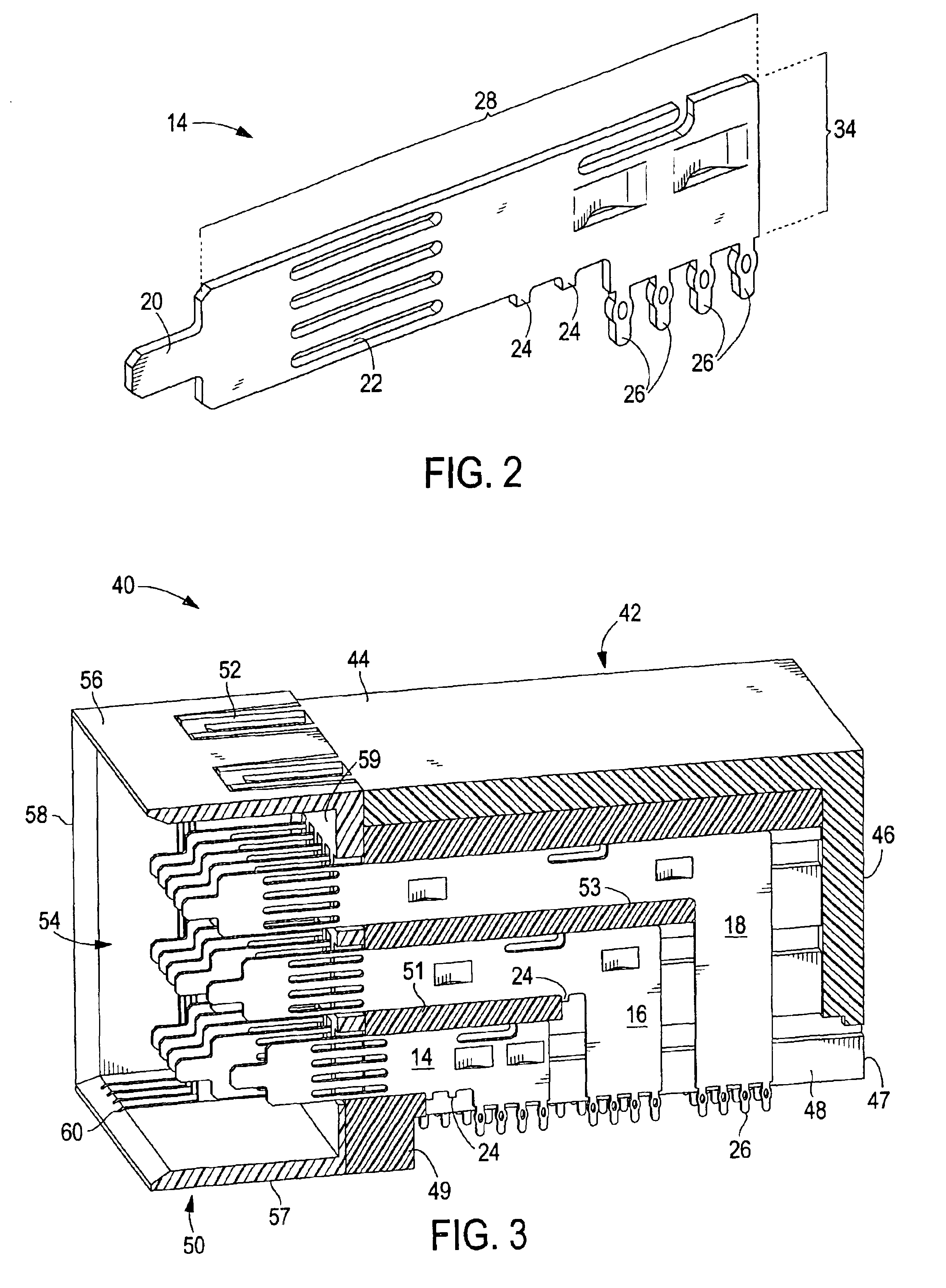
[0025]The plug lead frame element 14 includes an extension portion 28 formed integrally with, and connecting at a right angle to, a board transition portion 34. The plug lead frame element 16 includes...


PUM


Abstract

An electrical connector assembly comprising a housing having an interior chamber defining at least one lead frame plane, and identical sets of non-identical lead frame elements. The lead frame plane has a reference point. The lead frame elements are mounted in the interior chamber and aligned within at least one lead frame plane. The lead frame elements are adjustable along the lead frame plane between multiple levels with respect to the reference point. The multiple mating levels of the lead frame elements are created from only one lead frame. The mating levels are selected by the individual lead frame elements being positioned with respect to the reference point. The electrical connector also comprises N lead frame elements, each of which is adjustable between M mating levels to form X lead frame configurations, wherein X=MN.

Description

BACKGROUND OF THE INVENTION[0001]Certain embodiments of the present invention generally relate to improvements in electrical connectors and more particularly relate to multi-sequenced electrical connectors that include lead frames.[0002]Various electronic systems, such as computers, comprise a wide array of components mounted on printed circuit boards, such as daughtercards and motherboards, which are interconnected to transfer signals and power throughout the systems. The circuit boards are joined through electrical connectors. Typical connector assemblies include a plug connector and a receptacle connector, each of which may house a plurality of electrical contacts or wafers. An electrical wafer may be a thin printed circuit board or a series of laminated contacts within a plastic carrier. The electrical wafers within one connector may allow a daughter card to communicate with another daughter card through a backplane. Alternatively, the wafers may be mated in an orthogonal orient...

Claims


Application Information

Patent Timeline
IPC IPC(8): H01R43/20H01R13/648H01R24/00H01R107/00
CPCH01R12/725H01R43/20H01R12/7088
Inventor BROWN, JOHN B.WELLER, STEVEN A.
Owner TYCO ELECTRONICS LOGISTICS AG (CH)
Why Eureka
Try Eureka