Shadow mask assembly manufacturing method and cathode ray tube manufacturing method

Inactive Publication Date: 2005-05-10
PANASONIC CORP
View PDF22 Cites 7 Cited by
  • Summary
  • Abstract
  • Description
  • Claims
  • Application Information

AI Technical Summary

Benefits of technology

[0015]According to a fifth aspect of the present invention, in the shadow mask assembly manufacturing method, when the preliminary tension forces are applied, the preliminary tension forces are applied by forming at the four corners of the shadow mask three to eight through engagement holes each having a diameter of 3 mm to 8 mm and being located wi

Problems solved by technology

However, there is an issue that the planarity of the shadow mask will be impaired when the shadow mask attached to the support frame is subjected to heat treatment through a baking process, even when the shadow mask

Method used


Image

  • Shadow mask assembly manufacturing method and cathode ray tube manufacturing method
  • Shadow mask assembly manufacturing method and cathode ray tube manufacturing method
  • Shadow mask assembly manufacturing method and cathode ray tube manufacturing method

Examples


Embodiment Construction

[0033]Before the description of the present invention proceeds, it is to be noted that like parts are designated by like reference numerals throughout the accompanying drawings.

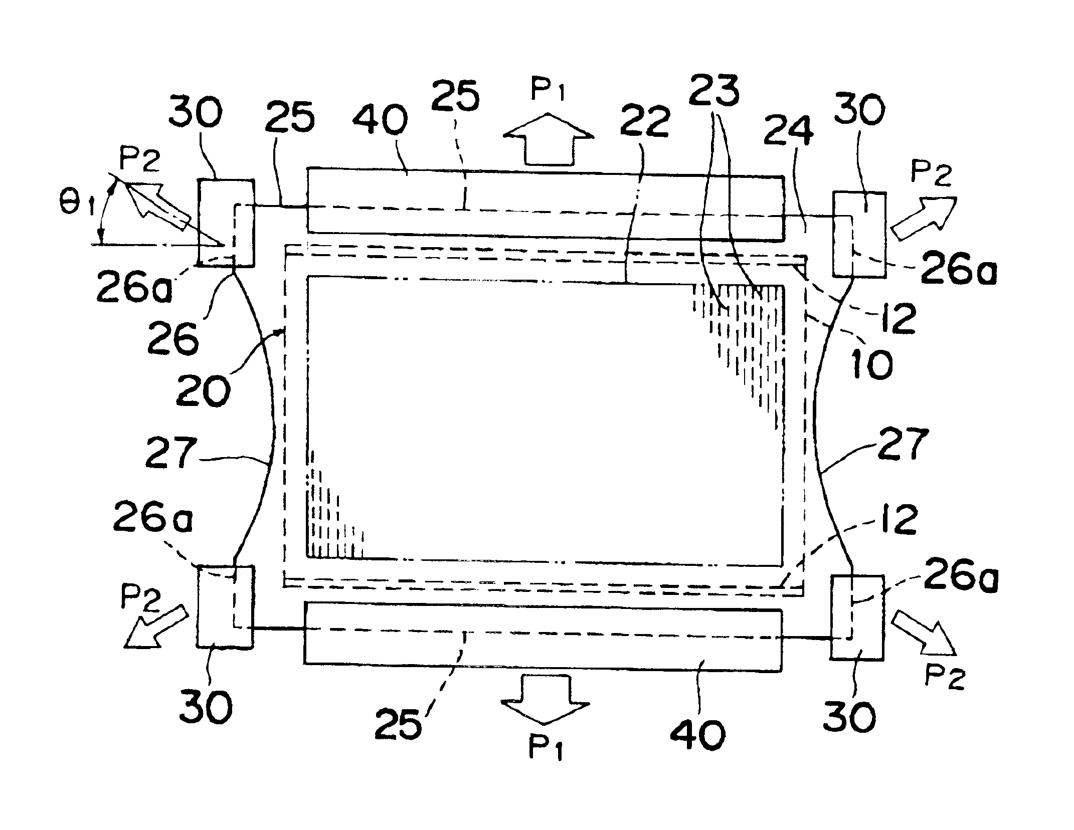
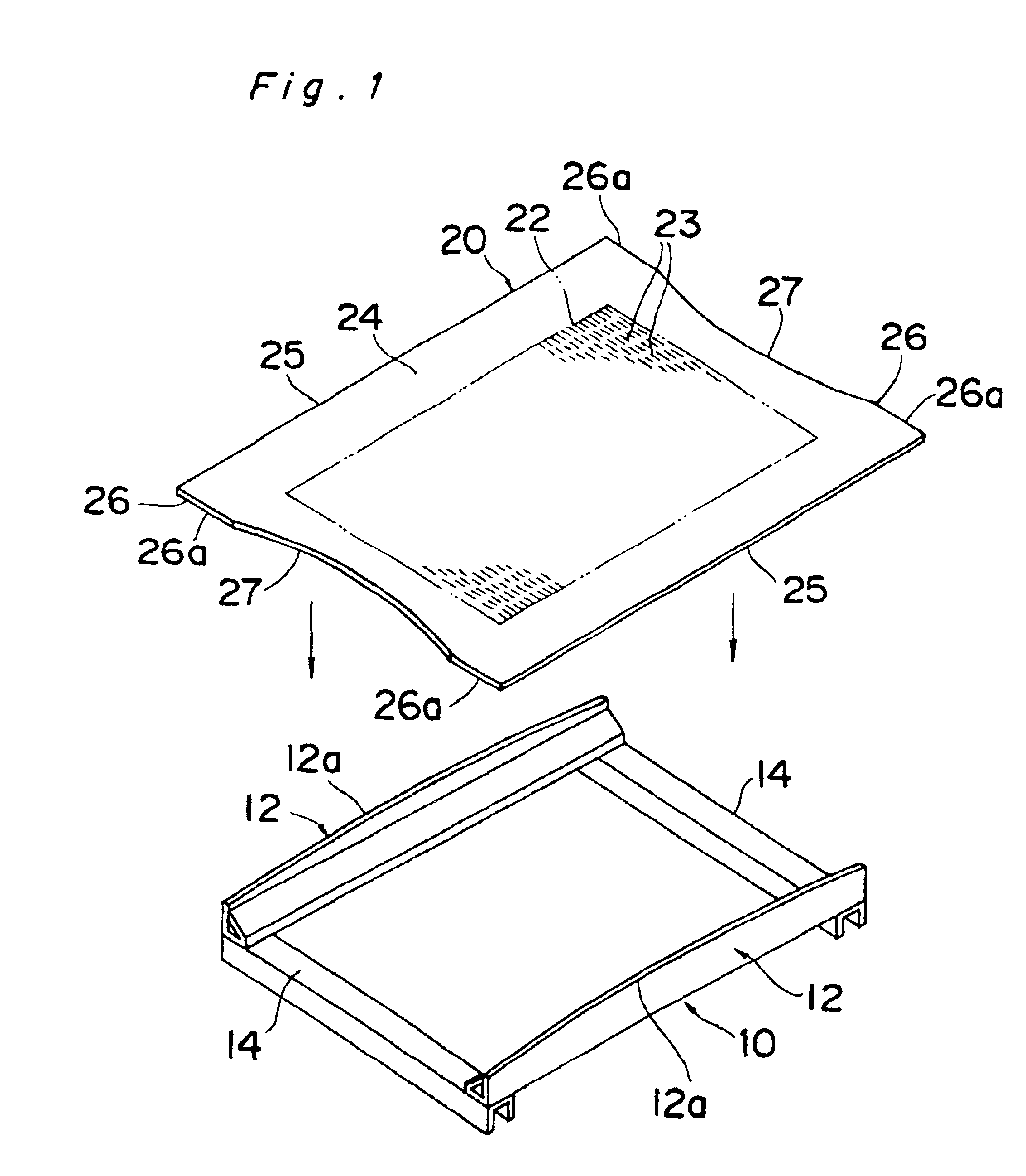
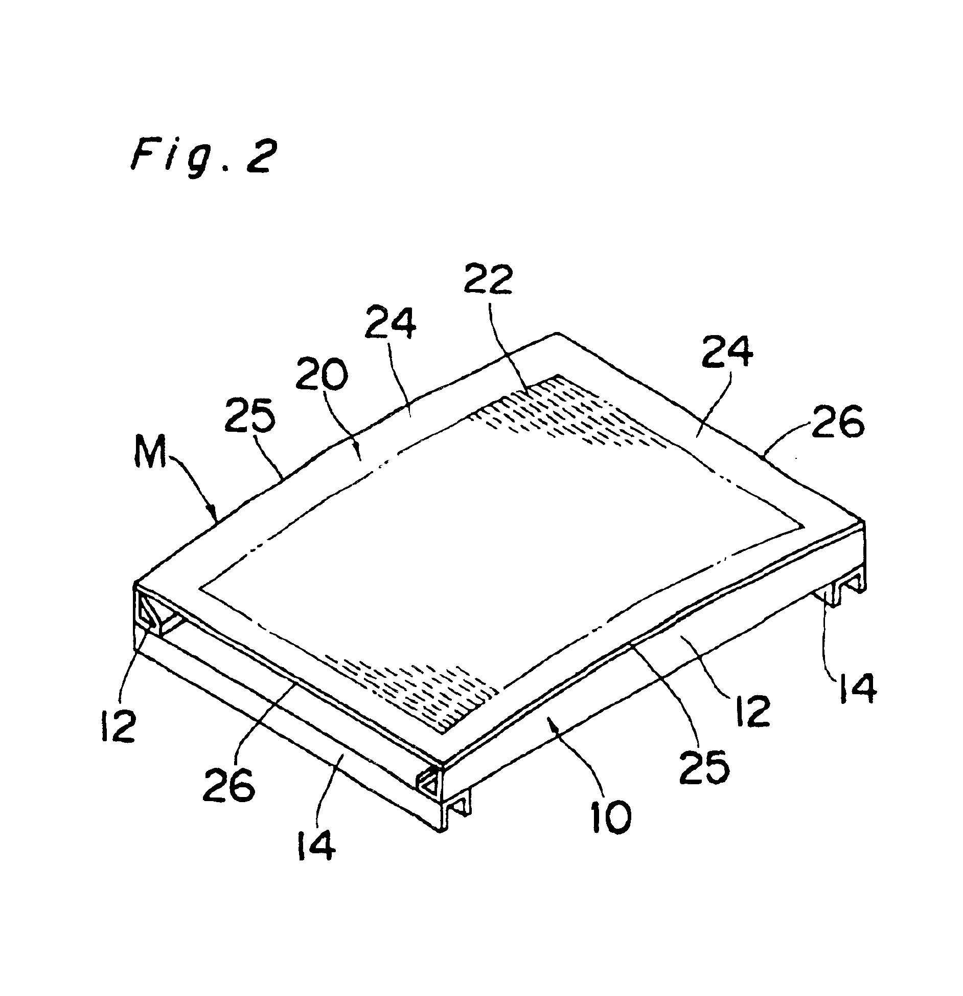
[0034]A method of manufacturing a shadow mask assembly according to one embodiment of the present invention, in which a shadow mask that has an approximately rectangular sheet-like shape and a perforation region provided with a number of through holes is fastened to a support frame that has an approximately rectangular frame-like shape in a tensioned state of the shadow mask method, comprises a process applying a preliminary tension force of an strength of 9.8 to 490 N to each of four corners of the shadow mask outwardly aslant with respect to a side of the shadow mask 20. A main tension force is applied to each of at least a pair of mutually opposite sides of the shadow mask outwardly perpendicularly to the sides after the preliminary tension force is applied; and the tensioned shadow mask to which the main ...


PUM


Abstract

A method of manufacturing a shadow mask assembly, in which a shadow mask is fastened to a support frame in a tensioned state, includes applying a preliminary tension force with a magnitude of 9.8 to 490 N to the four corners of the shadow mask outwardly aslant with respect to sides of the shadow mask. A main tension force is then applied to each of at least a pair of mutually opposite sides of the shadow mask outwardly perpendicularly to the sides. Thereafter, the shadow mask to which the main tension forces have been applied is fastened to the frame side of the support frame.

Description

BACKGROUND OF THE INVENTION[0001]The present invention relates to a shadow mask assembly manufacturing method and a cathode ray tube manufacturing method. In particular, the invention relates to a method of manufacturing a shadow mask which is a component of a cathode ray tube utilized for image display in a television receiver or the like. The shadow mask has minute holes through which an electron beam passes, and a support frame supports the shadow mask. The invention relates to a method of manufacturing the cathode ray tube with this shadow mask assembly incorporated therein.[0002]As a television receiver, a flat type television receiver having a flat image display surface, or a flat television receiver is known. In contrast to the conventional television receiver, the image display surface of which has a gently curved convex surface, the flat type television receiver has an almost flat image display surface, which is regarded as being able to display an image with good visibilit...

Claims


Application Information

Patent Timeline
IPC IPC(8): H01J9/14H01J9/02
CPCH01J9/142H01J2229/0716H01J9/02
Inventor NISHIKI, NAOMIYOKOYAMA, TOSINOBUUESUGI, YUJIIHARA, KIYOTAKATAKAKUWA, AYUMUMIWA, KIYOHITOIWAI, YOSHIKAZU
Owner PANASONIC CORP
Why Eureka
Try Eureka