Disk drive having magnetic head conduction paths with arrangements to control impedance

a technology of conduction path and magnetic head, applied in the direction of maintaining head carrier alignment, integrated arm assembly, instruments, etc., can solve the problem of unsuitable structure for high frequency recording operation, and achieve the effect of operating high frequency recording operation without increasing a cost-up asp

Inactive Publication Date: 2005-05-17
WESTERN DIGITAL TECH INC
View PDF6 Cites 17 Cited by
  • Summary
  • Abstract
  • Description
  • Claims
  • Application Information

AI Technical Summary

Benefits of technology

[0016]An object of the present invention is to provide a magnetic disk apparatus capable of realizing a high frequency recording operation operable higher than or equal to 200 MHz without increasing a cost-up aspect, while disclosing a novel structure of an electric wiring for a magnetic disk, and also a novel construction of a magnetic head recording unit.

Problems solved by technology

However, as previously explained, even when the electric wiring is merely formed on the suspension, it can be apparent that this structure is not suitable for the high frequency recording operation.

Method used


Image

  • Disk drive having magnetic head conduction paths with arrangements to control impedance
  • Disk drive having magnetic head conduction paths with arrangements to control impedance
  • Disk drive having magnetic head conduction paths with arrangements to control impedance

Examples


first embodiment

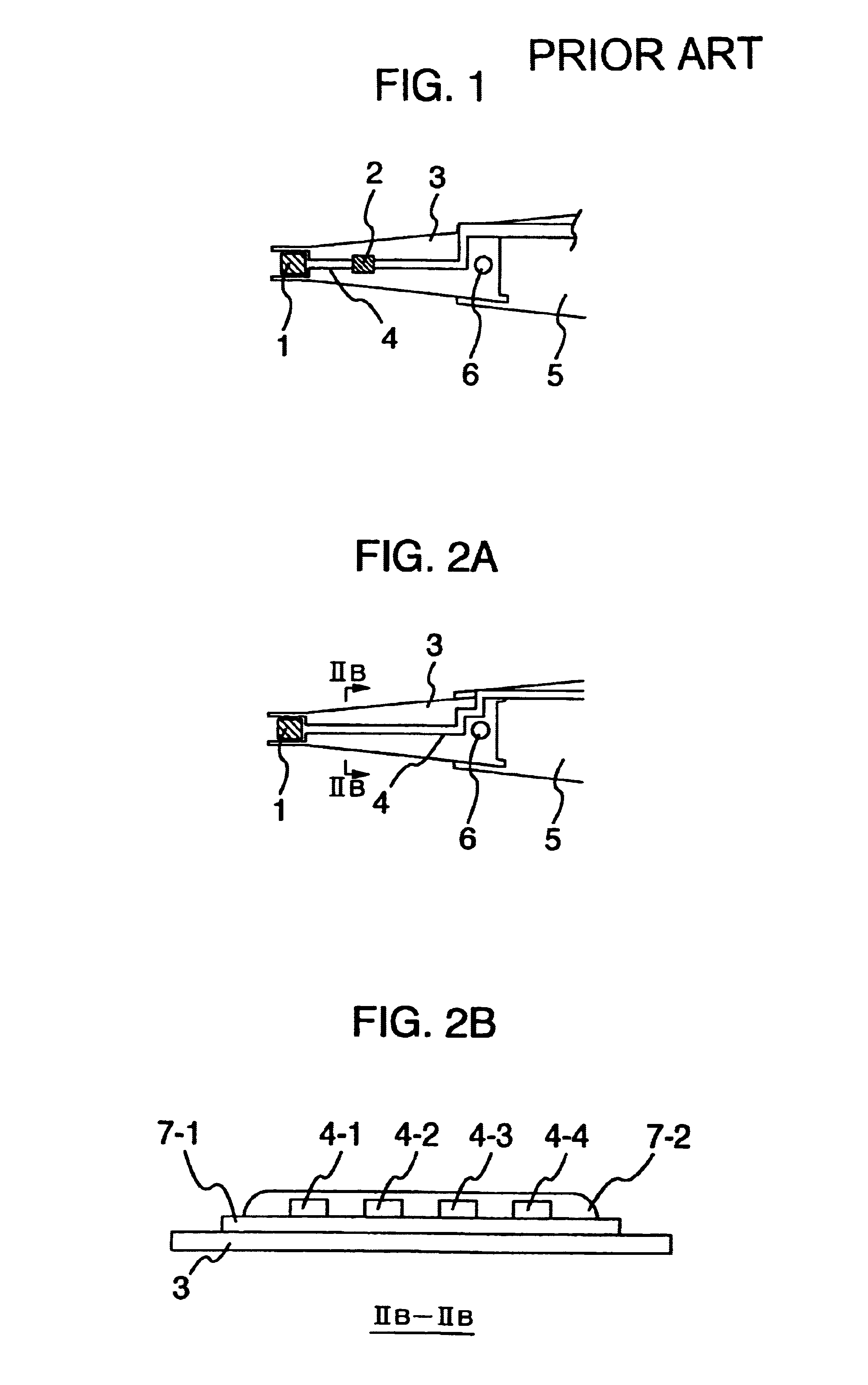
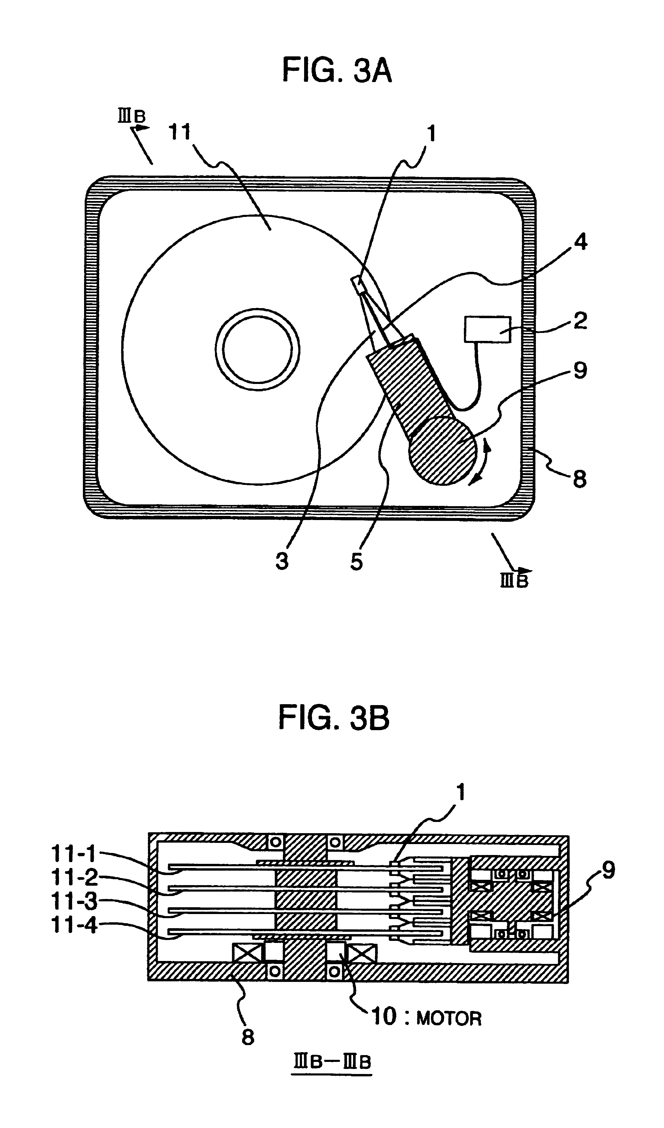
[0033]Referring now to FIG. 2 and FIG. 3, the present invention will be explained. FIG. 3 is a conceptional diagram for illustratively indicating a write unit of a magnetic disk apparatus for embodying the present invention. The write unit shown in FIG. 2 is constituted by a magnetic head 1, suspension 3, an arm 5, and an electric wiring 4. The magnetic head 1 converts electric information into magnetic information, and furthermore, realizes a read operation. The suspension 3 mechanically suspends the magnetic head, and produces depressing weight against a magnetic recording medium. The arm 5 supports this suspension 3. The electric wiring 4 functions as an electric signal transferring unit to the magnetic head. The electric wiring 4 is connected to a read / write IC for inputting / outputting an electric signal and for executing a signal process operation. This read / write IC is identical an IC2 shown in FIG. 3, and will be simply referred to as an “R / W IC” hereinafter.

[0034]As indicate...

second embodiment

[0054]As apparent from the above-explained measurement result, the above-explained feature owned by the electric wiring path having the higher characteristic impedance (disclosed in the present invention) may depend upon such a relationship between this characteristic impedance of the electric circuit path and the impedance of the magnetic head recording element unit. This may be understood as such an effect achieved by making the characteristic impedance of the electric circuit path higher than the impedance of the magnetic head recording element portion. It should also be noted that in the above-explained embodiment, this relationship is defined within all of the frequency ranges. Even when this relationship is limited to a narrower frequency condition so as to realize the present invention, a substantially same effect could be achieved. This example will now be described as a

[0055]The second embodiment is directed to a higher harmonic component contained in a recording current. I...

third embodiment

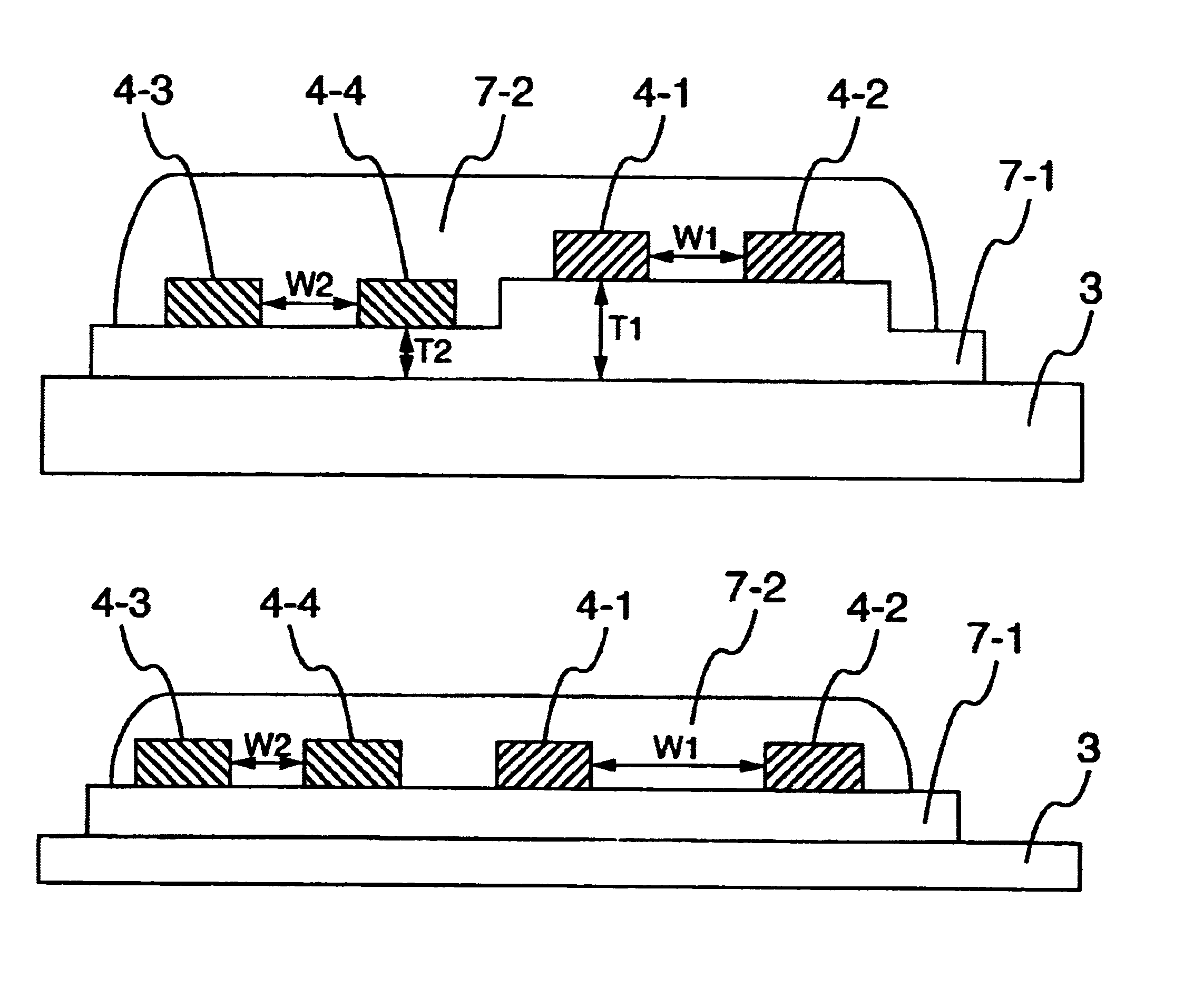
[0064]In the above-explained third embodiment, the magnetic head recording element unit is employed, the inductance of which is lower than or equal to 40 nH. This condition is caused by such a fact that the characteristic impedance of the electric wiring path is limited. The characteristic of the electric wiring path may be calculated from (inductance per unit length / capacitance per unit length) 1 / 2, assuming now that the electric wiring path is approximated to no loss. In order to increase the characteristic impedance, this inductance per unit length may be increased whereas the capacitance per unit length may be decreased. As is known, the inductance may be increased by widening the interval between the electric wiring paths. In order to reduce the capacitance, the width of the electric wiring path must be made narrower, or the material having the lower dielectric constant must be employed in the insulating layer. An allowable range is apparently determined when the interval betwe...


PUM

PropertyMeasurementUnit
frequencyaaaaaaaaaa
frequenciesaaaaaaaaaa
recording frequencyaaaaaaaaaa

Abstract

Magnetic disk apparatus includes an electric wiring capable of satisfying an electric condition under which high frequency recording higher than or equal to 200 MHz, a magnetic head having at least a recording device to a magnetic recording medium, and also the electric wiring corresponding to a recording current supplying device to this magnetic head are formed on a suspension member for mechanically suspending the magnetic head, the recording current being supplied to a magnetic head recording device by employing such electric wiring, the characteristic impedance of which is higher than a maximum impedance of the magnetic head recording device.

Description

[0001]This is a continuation application of U.S. Ser. No. 10 / 318,114, filed Dec. 13, 2002 now U.S. Pat No. 6,661,613; which is a continuation application of U.S. Ser. No. 10 / 126,576, filed Apr. 22, 2002, now U.S. Pat. No. 6,529,348; which is a continuation application of U.S. Ser. No. 09 / 523,383, filed Mar. 10, 2000, now U.S. Pat. No. 6,404,594.BACKGROUND OF THE INVENTION[0002]The present invention generally relates to a magnetic disk apparatus employed in a computer, an information processing apparatus, and so on. More specifically, the present invention is directed to a structure of a magnetic disk apparatus with employment of an electric wiring capable of satisfying an electric condition under which high frequency recording higher than or equal to 200 MHz can be realized in this magnetic disk apparatus.[0003]As storage apparatuses of information processing appliances, semiconductor memories and magnetic member memories are mainly employed. In view of access time, semiconductor me...

Claims


Application Information

Patent Timeline
Patent Type & Authority Patents(United States)
IPC IPC(8): G11B5/48G11B5/60
CPCG11B5/486G11B5/484
Inventor MARUYAMA, YOHJIIKEKAME, HIROSHITAKANO, HISASHI
Owner WESTERN DIGITAL TECH INC
Why Eureka
Try Eureka