Disk drive having magnetic head conduction paths with arrangements to control impedance
a technology of conduction path and magnetic head, applied in the direction of maintaining head carrier alignment, integrated arm assembly, instruments, etc., can solve the problem of unsuitable structure for high frequency recording operation, and achieve the effect of operating high frequency recording operation without increasing a cost-up asp
- Summary
- Abstract
- Description
- Claims
- Application Information
AI Technical Summary
Benefits of technology
Problems solved by technology
Method used
Image
Examples
first embodiment
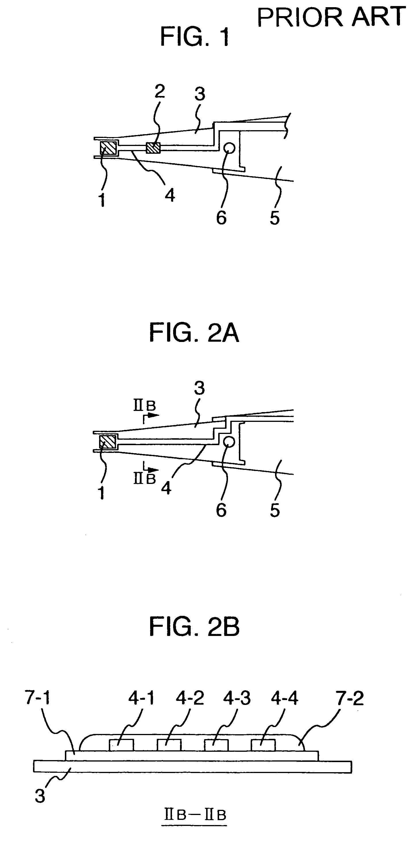
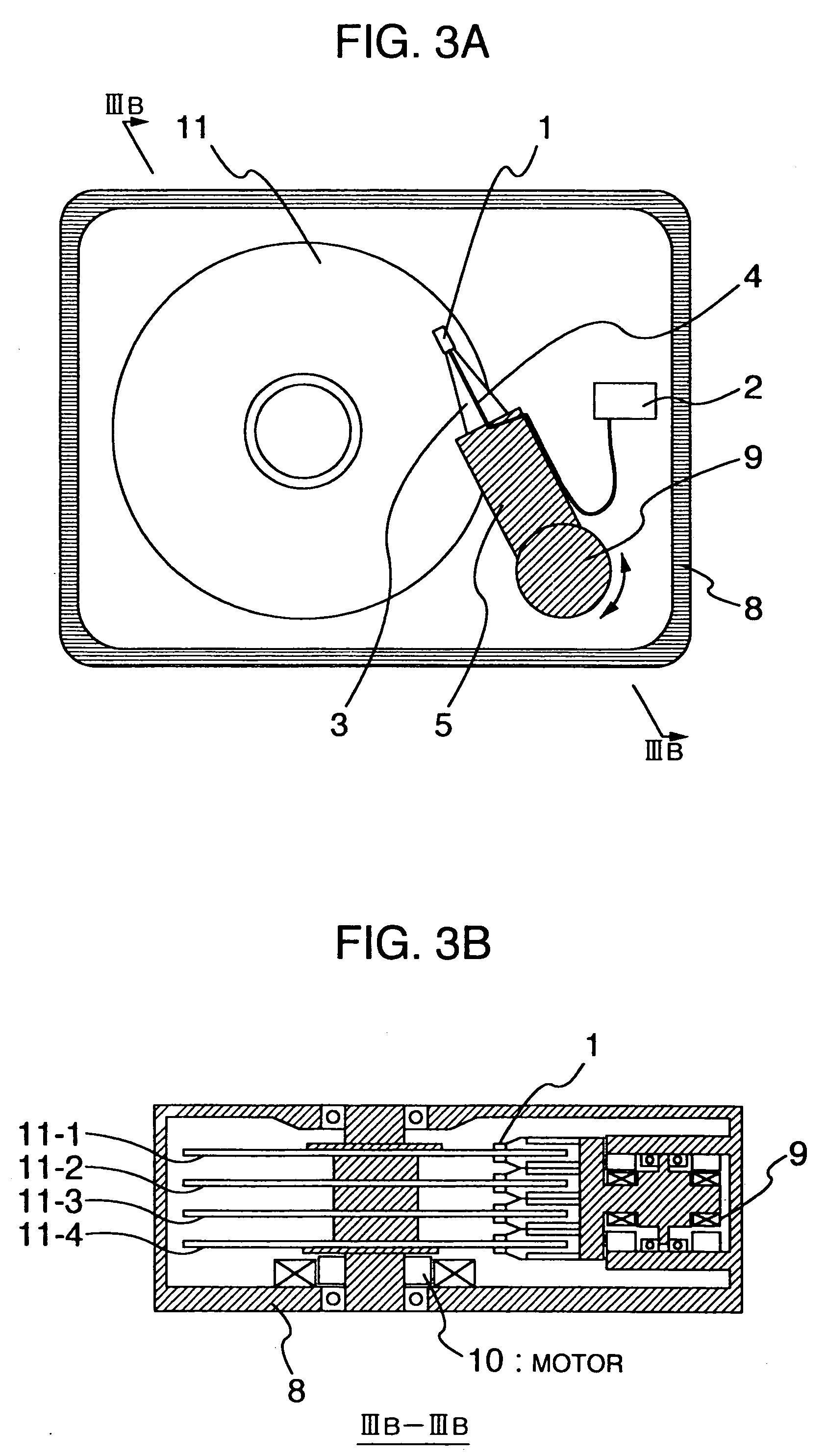
[0034]Referring now to FIG. 2 and FIG. 3, the present invention will be explained. FIG. 3 is a conceptional diagram for illustratively indicating a write unit of a magnetic disk apparatus for embodying the present invention. The write unit shown in FIG. 2 is constituted by a magnetic head 1, suspension 3, an arm 5, and an electric wiring 4. The magnetic head 1 converts electric information into magnetic information, and furthermore, realizes a read operation. The suspension 3 mechanically suspends the magnetic head, and produces depressing weight against a magnetic recording medium. The arm 5 supports this suspension 3. The electric wiring 4 functions as an electric signal transferring unit to the magnetic head. The electric wiring 4 is connected to a read / write IC for inputting / outputting an electric signal and for executing a signal process operation. This read / write IC is identical an IC2 shown in FIG. 3, and will be simply referred to as an “R / W IC” hereinafter.
[0035]As indicate...
second embodiment
[0055]As apparent from the above-explained measurement result, the above-explained feature owned by the electric wiring path having the higher characteristic impedance (disclosed in the present invention) may depend upon such a relationship between this characteristic impedance of the electric circuit path and the impedance of the magnetic head recording element unit. This may be understood as such an effect achieved by making the characteristic impedance of the electric circuit path higher than the impedance of the magnetic head recording element portion. It should also be noted that in the above-explained embodiment, this relationship is defined within all of the frequency ranges. Even when this relationship is limited to a narrower frequency condition so as to realize the present invention, a substantially same effect could be achieved. This example will now be described as a
[0056]The second embodiment is directed to a higher harmonic component contained in a recording current. I...
third embodiment
[0065]In the above-explained third embodiment, the magnetic head recording element unit is employed, the inductance of which is lower than or equal to 40 nH. This condition is caused by such a fact that the characteristic impedance of the electric wiring path is limited. The characteristic of the electric wiring path may be calculated from (inductance per unit length / capacitance per unit length)1 / 2, assuming now that the electric wiring path is approximated to no loss. In order to increase the characteristic impedance, this inductance per unit length may be increased whereas the capacitance per unit length may be decreased. As is known, the inductance may be increased by widening the interval between the electric wiring paths. In order to reduce the capacitance, the width of the electric wiring path must be made narrower, or the material having the lower dielectric constant must be employed in the insulating layer. An allowable range is apparently determined when the interval betwee...
PUM
| Property | Measurement | Unit |
|---|---|---|
| frequency | aaaaa | aaaaa |
| frequency range | aaaaa | aaaaa |
| width | aaaaa | aaaaa |
Abstract
Description
Claims
Application Information
 - R&D
- Intellectual Property
- Life Sciences
- Materials
- Tech Scout
- Unparalleled Data Quality
- Higher Quality Content
- 60% Fewer Hallucinations
Browse by: Latest US Patents, China's latest patents, Technical Efficacy Thesaurus, Application Domain, Technology Topic, Popular Technical Reports.
© 2025 PatSnap. All rights reserved.Legal|Privacy policy|Modern Slavery Act Transparency Statement|Sitemap|About US| Contact US: help@patsnap.com


