Portable folding utility table with frame connected to integral lip

a folding utility table and frame technology, applied in the field of utility tables, can solve the problems of unwieldy tables, inconvenient use, and many of these lightweight utility tables lack the sturdiness of the prior art heavy-weight utility tables

Inactive Publication Date: 2005-05-24
LIFETIME PRODUCTS
View PDF240 Cites 39 Cited by
  • Summary
  • Abstract
  • Description
  • Claims
  • Application Information

AI Technical Summary

Benefits of technology

[0018]The present invention is directed to a novel portable folding utility table having a center support assembly. The utility table includes a table top supported by a pair of support pedestals. In one presently preferred embodiment, the table top includes a mounting surface and a working surface formed opposite the mounting surface. The working surface may be textured and may include an integral outer periphery, at least a portion of which is beveled to provide comfort to a user.
[0021]In one presently preferred embodiment of the present invention, the retention assembly may include a single cross-brace member disposed through openings formed at the distal ends of the pivotal support braces and secured to the mounting surface. The mounting surface may be configured such that opposing ends of the cross-brace member are introduced through openings disposed in opposing sides of the mounting surface of the table top and may further include a mount for receiving and retaining the cross-brace member therein. Thus, the distal ends of both support pedestals are preferably attached along the length of the cross-brace member which is secured to the mounting surface, thereby reducing the number of attachment mechanisms and interrelating the support pedestals to the table top to increase structural support and efficiency of manufacture.
[0022]In another presently preferred embodiment, each support pedestal includes a first member pivotally engaging the mounting surface of the table top and a second member configured for telescoping engagement with the first member. This configuration permits the height of the support pedestal to be disposed between a lengthened position and a retracted position.
[0023]In an alternative presently preferred embodiment, the table may include two cross-brace members providing separate attachment points for the first and second pivotal support braces. Such a configuration is particularly desirable for tables having an extended length, in which it may not be advantageous for each of the pivotal support braces to have lengths sufficient for extending into the center of the table top. Correspondingly, a dual cross-brace configuration may provide additional space for accommodating one or more user's legs under the table top.
[0024]Moreover, in yet another presently preferred embodiment of the present invention, each support pedestal may include two legs slightly offset from the corresponding legs of the other support pedestal disposed on the opposing side of the table top, so that longer support legs can be accommodated under a smaller table top when disposed above an underlying surface. This off-set distance is sufficient to keep the support legs of the opposing support pedestal from interfering with one another, thus allowing displacement substantially against the mounting surface of the table top when disposed in the retracted position for storage.

Problems solved by technology

A major drawback with many portable folding utility tables of the prior art, however, is their inherent size and bulkiness.
Moreover, some prior art portable folding utility tables are heavy enough to cause injury if dropped or mishandled.
These unwieldy tables are usually made from hardwood, particle board, or similarly heavy materials.
However, many of these lightweight utility tables generally lack the sturdiness of the heavier-weight prior art utility tables.
Another disadvantage to prior art utility tables is the means used for attaching the table support legs or two or more support pedestals to the underside of the table.
This means of attachment may compromise the integrity of the table top thereby making it weaker at the point of attachment between the table support legs and the table top.
Often, however, this means of attachment by bonding weakens the structural integrity of the table top.
Thus, when the table support legs fail, a portion of the material forming the table top may pull away at the point of the bonded attachment thereby making the table costly, if not impossible to repair.
These types of attachment mechanisms, however, are normally heavier, more costly, more difficult to install, and typically require additional time to manufacture.
The previously stated disadvantages are compounded by the fact that many prior art utility tables incorporate a separate and distinct attachment mechanism for attaching each table support leg or pedestal to the table top.
One particular problem with utility tables having separate and distinct attachment mechanisms is that they are generally susceptible to bowing in the center of the table top under stress.
Yet another drawback with many prior art utility tables is that the hard materials used to maintain a sufficient rigidity and sturdiness of the table top often have sharp edges which may be uncomfortable for the user to lean against or rest their arms upon.
Further, these materials may also be susceptible to damage or degradation from the elements of nature.
In addition, smaller utility tables that are found in the prior art usually comprise shortened support legs that fail to provide sufficient height to the table top in relation to the underlying surface, thus these types of table are generally uncomfortable to users.
Small folding utility tables of the prior art are also typically bulky when disposed in the folded position because complex and unwieldy mechanisms are generally required to accommodate the use of longer support legs that may be incorporated to overcome the inherent height deficit found in most smaller utility tables.

Method used


Image

  • Portable folding utility table with frame connected to integral lip
  • Portable folding utility table with frame connected to integral lip
  • Portable folding utility table with frame connected to integral lip

Examples


Embodiment Construction

[0033]It will be readily understood that the components of the present invention, as generally described and illustrated in the Figures herein, could be arranged and designed in a wide variety of different configurations Thus, the following more detailed description of the embodiments of the assembly and method of the present invention, as represented in FIGS. 1 through 5, is not intended to limit the scope of the invention, as claimed, but it is merely representative of the presently preferred embodiments of the invention.

[0034]The presently preferred embodiments of the invention will be best understood by reference to the drawings, wherein like parts are designated by like numerals throughout.

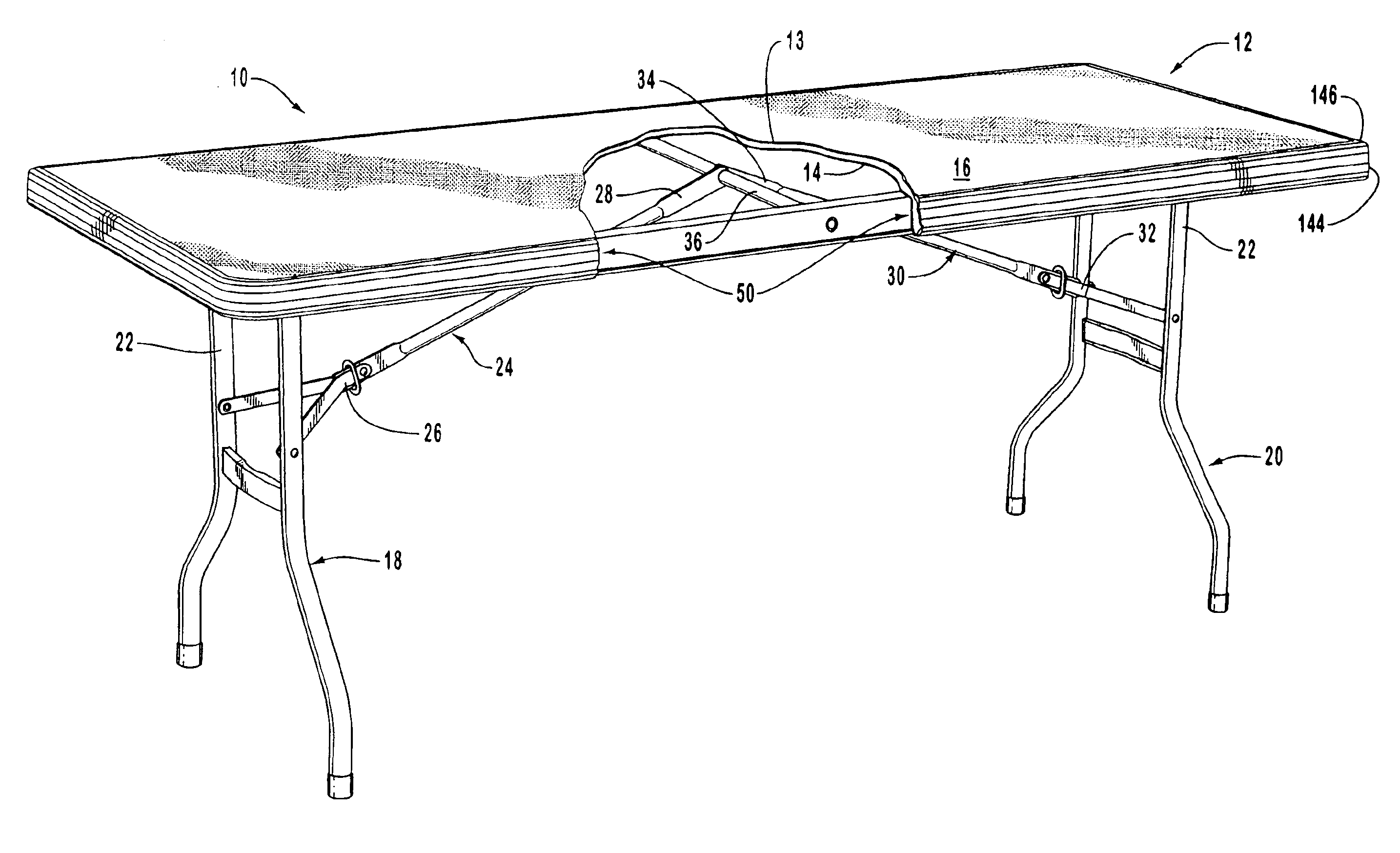
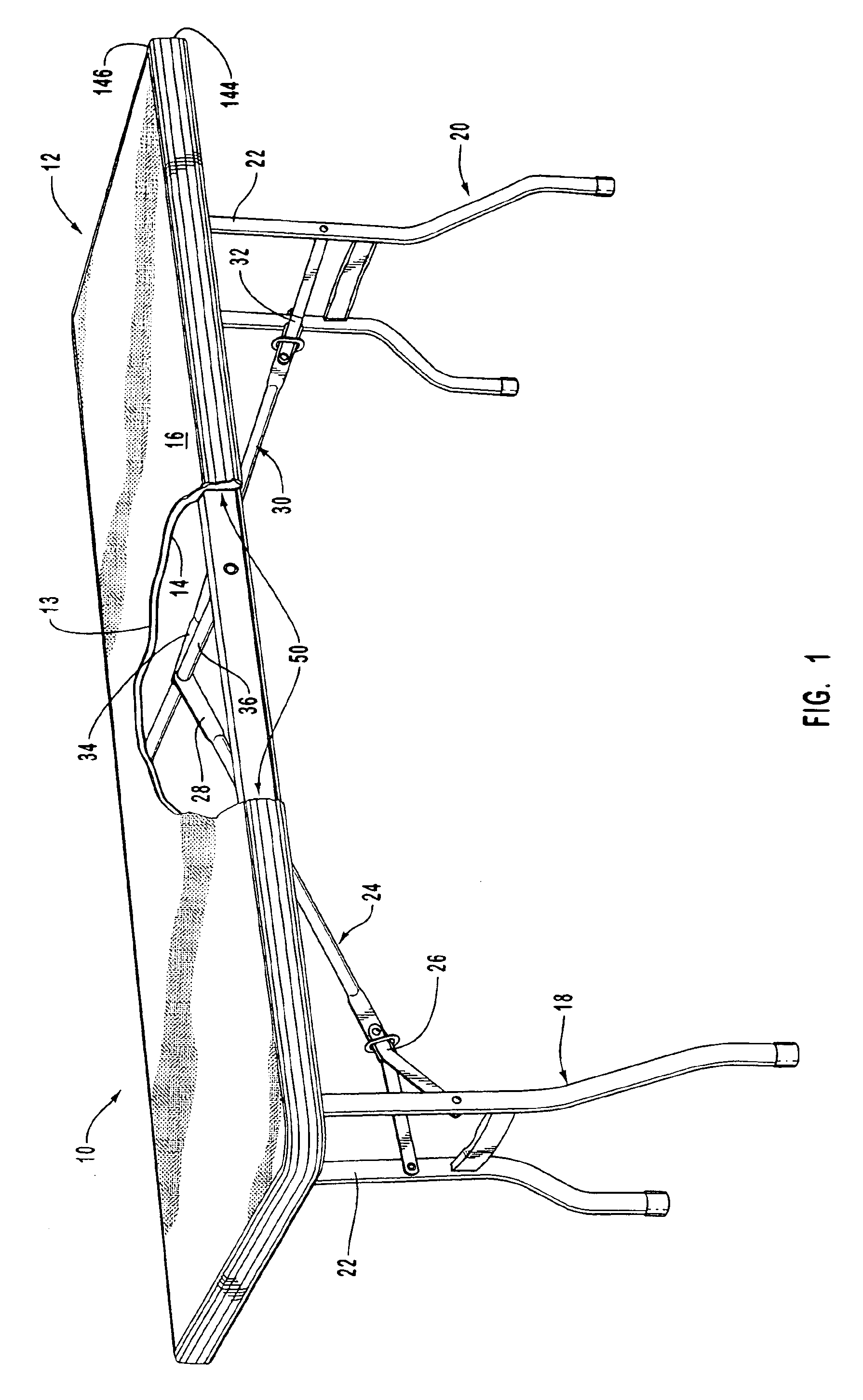
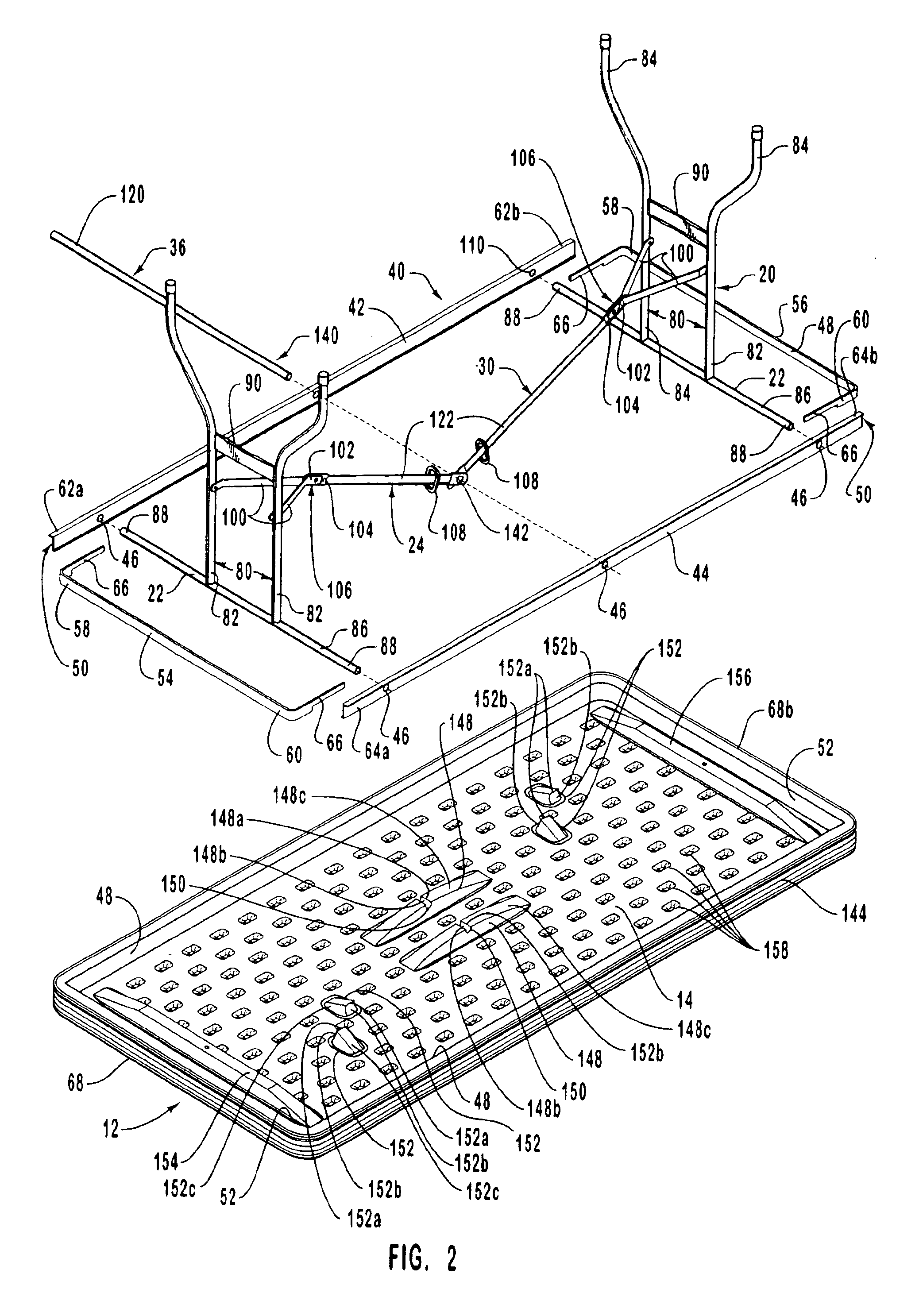
[0035]One presently preferred embodiment of the present invention, designated generally at 10, is best illustrated in FIGS. 1 and 2. As shown, with particular reference to FIG. 1, a utility table according to the present invention is generally designated at 10. The utility table 10 preferably...


PUM

PropertyMeasurementUnit
thicknessaaaaaaaaaa
heightaaaaaaaaaa
heightaaaaaaaaaa

Abstract

A pivotable folding utility table includes a table top having a pair of support pedestals pivotally attached thereto. A first pivotal support brace including a distal end and a proximal end attached to the first support pedestal. A second pivotal support brace including a distal end and a proximal end attached to the second support pedestal. The distal ends of the first and second pivotal support braces pivotally attached to a retaining assembly preferably mounted in relation to the table top. Specifically, the retaining assembly includes a cross-brace member operably disposed through openings formed in the distal ends of the first and second pivotal support braces, thus providing a pivotal engagement in relation to the table top. Alternatively, a second retaining assembly including a cross-brace member may be mounted in relation to the table top, wherein the distal end of the first pivotal support brace pivotally engages the first retaining member and the distal end of the second pivotal support brace pivotally engages the second retaining member. In addition, the first and second support pedestals may comprise at least one support leg, wherein each support leg of the first and second support pedestals are laterally offset from each other so as to permit an offset displacement of the support legs when the support pedestals are disposed in a collapsed position.

Description

CROSS-REFERENCE TO RELATED APPLICATIONS[0001]The present application is a continuation of U.S. patent application Ser. No. 10 / 097,037, filed Mar. 12, 2002, entitled PORTABLE FOLDING UTILTY TABLE WITH FRAME CONNECTED TO INTEGRAL LIP now U.S. Pat. No. 6,655,301; which is a continuation of patent application Ser. No. 09 / 635,303, filed Aug. 9, 2000, entitled PORTABLE FOLDING UTILITY TABLE WITH CENTER SUPPORT ASSEMBLY, now U.S. Pat. No. 6,431,092; which is a continuation-in-part of U.S. patent application Ser. No. 09 / 228,326, filed Jan. 11, 1999, entitled PORTABLE FOLDING UTILITY TABLE WITH CENTER SUPPORT ASSEMBLY, now U.S. Pat. No. 6,112,674; which is a continuation-in-part of U.S. patent application Ser. No. 29 / 095,372, filed Oct. 21, 1998, entitled UTILITY TABLE, now U.S. Pat. No. Des. 414,626 and U.S. patent application Ser. No. 29 / 105,094, filed May 17, 1999, entitled UTILITY TABLE, now U.S. Pat. No. Des. 419,332, all of which are incorporated herein by reference in their entireties...

Claims


Application Information

Patent Timeline
Patent Type & Authority Patents(United States)
IPC IPC(8): A47B3/00A47B3/091
CPCA47B3/091A47B3/0912A47B13/08B29C49/20A47B3/08B29D7/00A47B3/0809B32B3/085B32B3/30A47B13/02A47B3/0911Y10T428/24008B29C49/00B29C49/0031B29C49/04B29C2049/2008B29K2023/065B29K2105/0032B29K2105/0044B29K2105/16B29L2031/448Y10S108/901Y10T428/24479Y10T428/1352Y10T428/24182Y10T29/49947Y10T29/4998Y10T29/49826
Inventor STANFORD, CARL R.
Owner LIFETIME PRODUCTS
Why Eureka
Try Eureka