

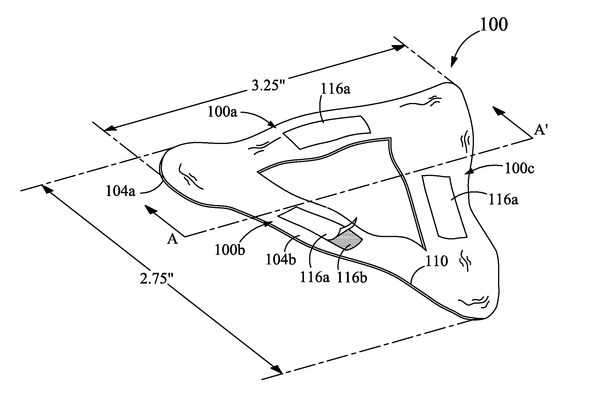
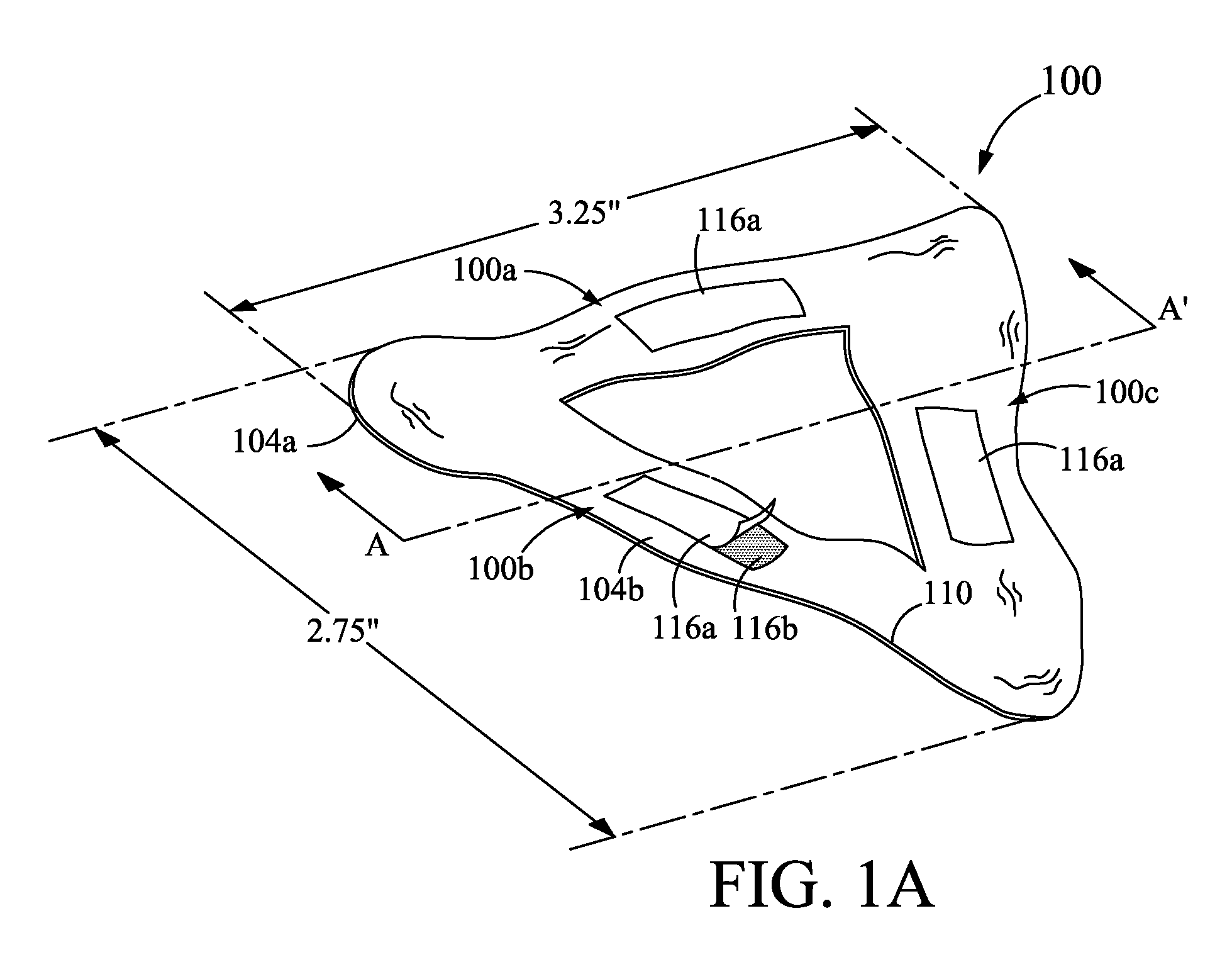
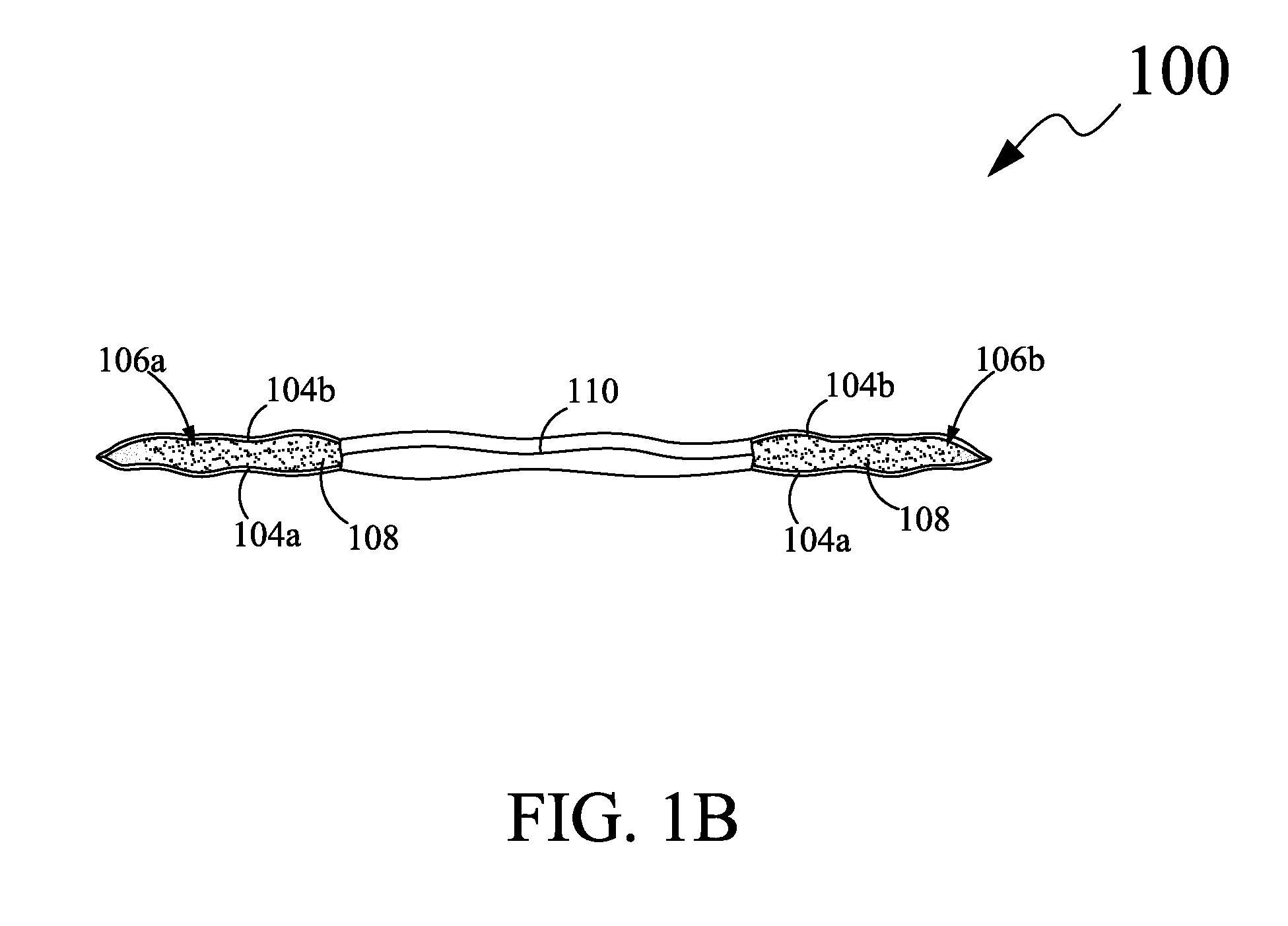
Respiratory mask interface
a technology for respiratory masks and interfaces, applied in respiratory masks, inhalators, life-saving devices, etc., can solve problems such as discomfort for users, increased temperature and humidity of respiratory masks, and sweating on an area enclosed by respiratory masks
- Summary
- Abstract
- Description
- Claims
- Application Information
AI Technical Summary
Benefits of technology
Problems solved by technology
Method used
Image

Examples
Embodiment Construction
[0019]The exemplary embodiments described herein detail for illustrative purposes are subject to many variations in composition, structure, and design. It should be emphasized, however, that the present disclosure is not limited to a particular interface for a respiratory mask, as shown and described. It is understood that various omissions and substitutions of equivalents are contemplated as circumstances may suggest or render expedient, but these are intended to cover the application or implementation without departing from the spirit or scope of the claims of the present disclosure. Also, it is to be understood that the phraseology and terminology used herein is for the purpose of description and should not be regarded as limiting.
[0020]Unless limited otherwise, the terms “coupled,”“attached,” and variations thereof herein are used broadly and encompass direct and indirect arrangements. The terms “first,”“second,” and the like, herein do not denote any order, elevation or importa...
PUM
 Abstract
Description
Claims
Application Information