System, method and tool for ensuring correct insertion of an artificial hip joint

a hip joint and hip joint technology, applied in the field of orthopaedic surgery, can solve the problems of increasing the risk of dislocation, difficult practice practice accurate alignment of the prosthesis stem in the femoral canal, and the head of the prosthesis to the lever, so as to achieve reliable compensation, improve the effect of flexibility and good alignment of the parts involved

Inactive Publication Date: 2009-03-19
OM SURGICAL UK
View PDF13 Cites 35 Cited by
  • Summary
  • Abstract
  • Description
  • Claims
  • Application Information

AI Technical Summary

Benefits of technology

[0050]When using the measuring device, the connection members are brought in contact with the receptors at both supports. The adjustable member and the length of said first or said second arm is then adjusted so that the connection members and the corresponding receptor rests are in full contact with each other. In the illustrated embodiment where the receptors are grooves, the position of the adjustable member and the adjustable arm are adjusted until the connection members rest in the grooves and is in contact with the bottom of the groove at most or all of the length of the connection members. It is preferred that the adjustable member comprises means to lock the adjustable member in a preferred position along the main body. By locking the adjustable member relative to the main body, unintentional movement of the adjustable member relative to the main body after performing the measurement is avoided.
[0053]According to a preferred embodiment, substantially parallel bores are made in the main body and the adjustable member. Said bores provides firm fixation for drill sheaths in using the measuring device as a drill guide and for correct positioning of screws or nails into the patients' femur and pelvis and for fixation of the supports including the receptors. Alternatively, a bent curvature, preferably a hemicircle shape, is provided in the main body of the measurement device in order to provide a drill support surface having easy access.
[0054]The improved measurement device provides a more flexible measurement system and provides good alignment of the parts involved in relation to each other in order to provide as much comfort for the surgeon as well as the patient. The measurement device provides both length and orientation measures as a result of its unique advantageous design.
[0055]Furthermore, the measuring device provides for reliable compensation of variations of the hip prosthesis stem in the femur.

Problems solved by technology

However, as the tension of the soft tissues surrounding the joint, e.g. the joint capsule etc. is weakened after the operation is possible for the patient to place the leg in a position outside its normal range of movement.
This may cause the head of the prosthesis to lever out of the cup (dislocation).
Moreover, it is important that “natural” movements of the leg do not bring the joint in positions where the neck of the prosthesis rides on the edge of the cup as this may result in dislocation through simple leverage.
The risk of dislocation is considered increased in patients whose prosthesis components are inserted in an incorrect mutual positioning, than in those where the mutual positioning of the components (i.e. the spatial interface between the components) is correct.
Thus a prosthesis joint where the cup is angled forwards at 10 degrees and the prosthesis stem is angled forwards at 20 degrees will result in a ROM for the patient that is nearly as adequate as if both components were angled forward at 15 degrees, the sum of the forward angling being 30 degrees is both cases During the fixation of the prosthesis stem, accurate alignment of the prosthesis stem in the femoral canal may be difficult in practice, especially if the stem is to be fastened cement free.
These instruments are handles onto which the cup is fastened during the insertion but they do not have any means for assuring the correct position and direction of the cup.
Additionally, these publications do only describe devices and means for insertion of one of the prosthesis parts, i.e. the prosthesis stem, and does not describe any means to ensure an intended mutual angle between the cup and the prosthesis stem.
This device, however, may not be used by itself to assure the mutual positioning between the prosthesis parts when using cups to be mounted without the use of cement.
Additionally it may only be used to assure that the parts of the prosthesis is positioned correctly relative to each other, but does not take into consideration the correct insertion relative to the patient.
The bone coverage for the cup is often inferior when the cup is correctly mounted.
This number is not sufficient to obtain and maintain the skills and routine required to achieve good surgical results.
The computer based tool according to W002 / 080824 is, however, relatively expensive and complicated and requires high technical skills besides the surgical skills.
Working through small incisions is, however, more demanding than traditional surgery.
For hip joint prosthesis surgery the main problem is related to the position of the parts of the prosthesis.
As these systems are expensive, complicated and demanding to use they are mainly employed in a limited number of university clinics, while smaller hospitals cannot afford this technology or have not the specially trained human resources to man them.
Leg length discrepancy after total hip replacement is a well known and frequent complication.
The device according to WO 01 / 30247 comprises a level fixation means, which may ensure that the foot is pointing upwards, but if the leg of the patient is pointing in another direction after the insertion of the prosthesis than before, this will result in a wrong positioning of the patient's leg.
Thus, it is impossible to assure that exactly the same three-dimensional direction of the leg is obtained.
However, it is not in all cases possible to exactly restore preoperative hip biomechanics after replacement of the hip joint due to mechanical limitations of the artificial hip joint prosthesis.
While increased offset after Total Hip Replacement increased Range of Motion by reducing femoropelvic impingement, and increased abductor muscle tension through increased abductor muscle lever arm, complications include increased rotational torque on the prosthesis stem, which may lead to prosthesis loosening.
The offset of a prosthesis joint is difficult to control as a number of prosthesis parameters may influence the result, e.g. stem CCD angle other than the typical 135 deg; medial or lateral shift of the neck union due to valgus or varus orientation of the shaft—or—medialisation or lateralisation of the new joint socket mounted in the pelvis.

Method used


Image

  • System, method and tool for ensuring correct insertion of an artificial hip joint
  • System, method and tool for ensuring correct insertion of an artificial hip joint
  • System, method and tool for ensuring correct insertion of an artificial hip joint

Examples


Embodiment Construction

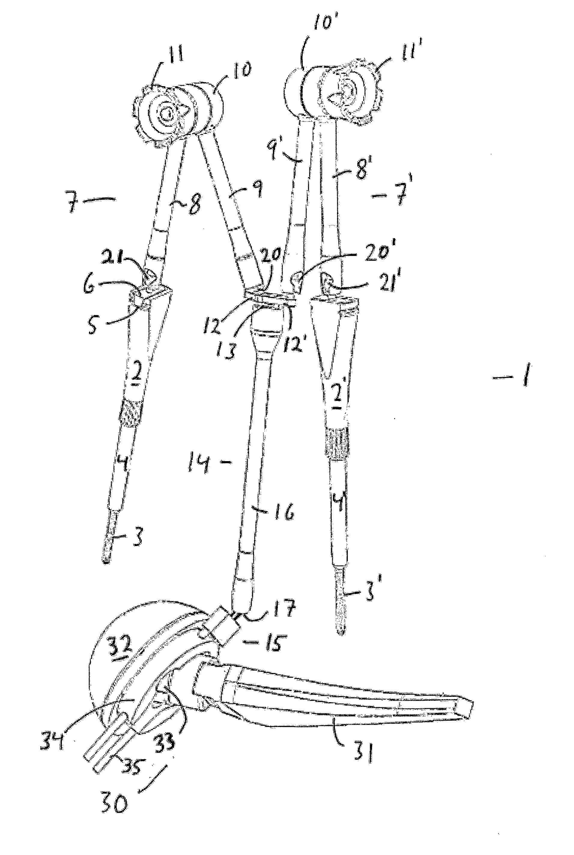
[0088]Proper control over leg length and offset during total hip replacement can only obtained through comparison of a series of repeated measurements.

[0089]1) The first measurement is performed as a combination of measurements on preoperative x-rays and clinical measurements on the patient performed in the outpatient clinic when the surgery is planned.

[0090]2) The next measurement is performed between a pelvic and a femoral landmarks performed in the early stage of the surgery, before the femoral neck is divided. For full control of the procedure, two more measurements should be carried out,

[0091]3) One measurement should be carried out during a trial reduction of the joint with temporary prosthesis components and

[0092]4) One when the actual components have been inserted still though, with a choice between different neck lengths.

[0093]A series of measurements as described above enables the surgeon to choose prosthesis components (stage 3 to 4) to achieve the measurements that were ...


PUM


Abstract

The present invention relates to the area of orthopaedic surgery, and in particular to a system for ensuring that prosthesis components or parts thereof are inserted correctly upon implantation of artificial hip joints and to methods for ensuring correct insertion of the parts of an artificial hip joint or femoral prosthesis during surgery. This system comprises a tool (30) for controlling the mutual positioning of the main components in a hip prosthesis, a measuring device (40), for measuring the distance between two supports connected to the patient's pelvis and leg, and connection members (46, 47) arranged at said measuring device, where said connection members are adapted to interact with receptors at said supports.

Description

FIELD OF THE INVENTION[0001]The present invention relates to the area of orthopaedic surgery, and in particular to a system for ensuring that prosthesis components or parts thereof are inserted correctly upon implantation of artificial hip joints and to methods for ensuring correct insertion of the parts of an artificial hip joint or femoral prosthesis during surgery.BACKGROUND OF THE INVENTION[0002]An artificial hip joint has two main components; a prosthesis stem and a socket which is often referred to as “the cup”. One end of the prosthesis stem is provided either with a spherical ball head or a prosthesis neck, which may be modular and designed so that the neck may rotate in the stem, on which stem a ball head may be placed. Said ball head is designed for a close, sliding fit in a spherical recess in the cup. Together, the prosthesis stem / neck with the ball head and the cup will act as a ball joint to replace the natural hip joint.[0003]The other end of the prosthesis stem compr...

Claims


Application Information

Patent Timeline
Patent Type & Authority Applications(United States)
IPC IPC(8): A61B17/58
CPCA61B5/1072A61F2250/0006A61F2/32A61F2/34A61F2/36A61F2/3662A61F2/38A61F2/4657A61F2/4684A61F2002/30153A61F2002/30538A61F2002/3611A61F2002/365A61F2002/4631A61F2002/4635A61F2002/4658A61F2002/4668A61F2230/0019A61B5/4528
Inventor IVERSEN, BJORN FRANC
Owner OM SURGICAL UK
Why Eureka
Try Eureka