Electrical connector

a technology of electric connectors and connectors, applied in the direction of electrical equipment, coupling device connections, securing/insulating coupling contact members, etc., can solve the problems of erroneous recognition of the second locking position as the main locking position, requiring a large amount of space, and unable to easily push the retainer 330/b> that is in the temporary locking position into the main locking position

Inactive Publication Date: 2006-10-03
TYCO ELECTRONICS JAPAN GK
View PDF12 Cites 25 Cited by
  • Summary
  • Abstract
  • Description
  • Claims
  • Application Information

AI Technical Summary

Benefits of technology

[0017]It is therefore an object of the present invention to provide an electrical connector that can prevent any unintentional movement of the retainer from the temporary locking position to the main locking position without making the retainer susceptible to damage or requiring a large amount of space.

Problems solved by technology

Consequently, the retainer 330 that is in the temporary locking position cannot be easily pushed into the main locking position.
Therefore, two kinds of locking arms are needed, which requires a large amount of space.
Moreover, since there are two temporary locking positions, there is a danger that the second locking position P2 will erroneously be recognized as the main locking position.

Method used


Image

  • Electrical connector
  • Electrical connector
  • Electrical connector

Examples


Embodiment Construction

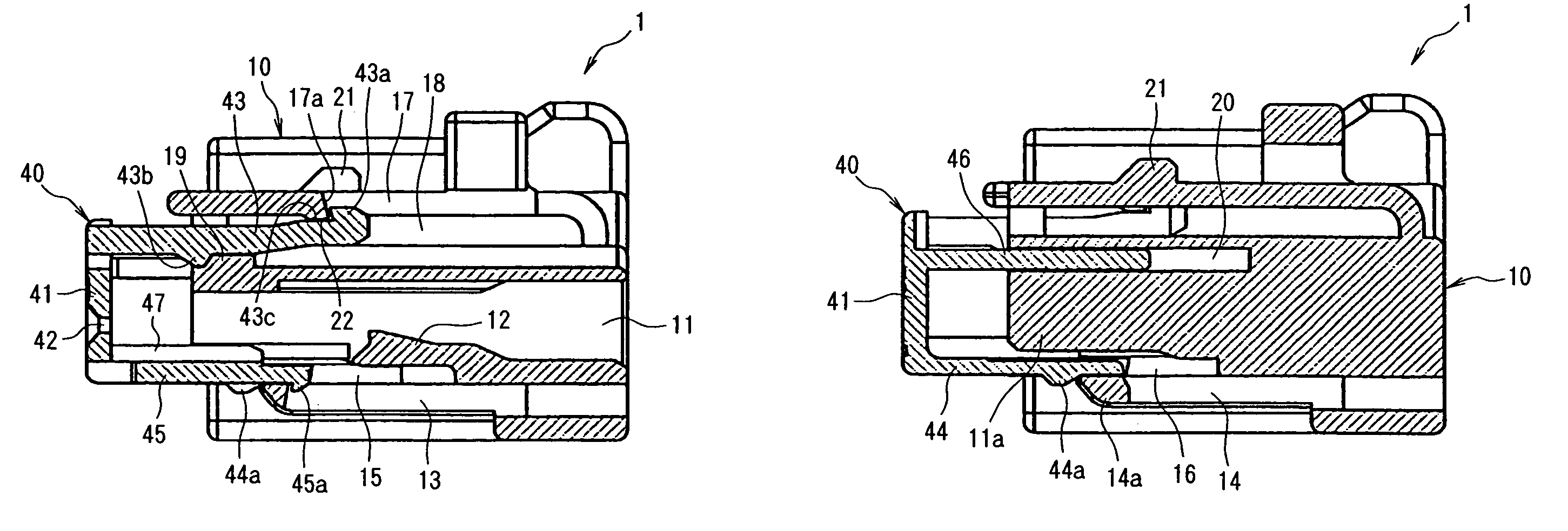
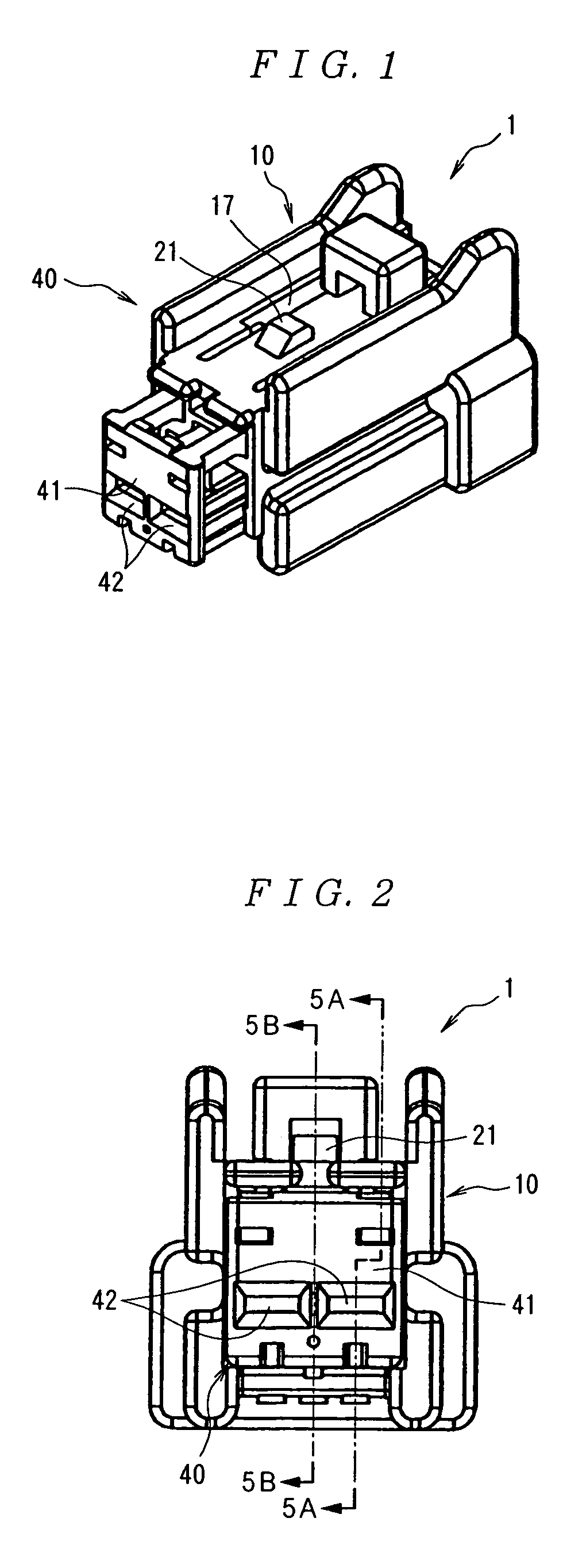
[0038]FIG. 1 shows an electrical connector 1. The electrical connector 1 includes an insulating housing 10 and a retainer 40. The housing 10 has a substantially rectangular shape and is formed by molding an insulating synthetic resin. As shown in FIG. 5A, a plurality of contact accommodating cavities 11 extends in a single row in the housing 10. As shown in FIGS. 8A and 8B, each of the contact accommodating cavities 11 opens on a front side of the housing 10 (left side in FIGS. 1, 8A, and 8B). As shown in FIG. 5B, a partition wall 11a that extends in the left-right direction separates the contact accommodating cavities 11.

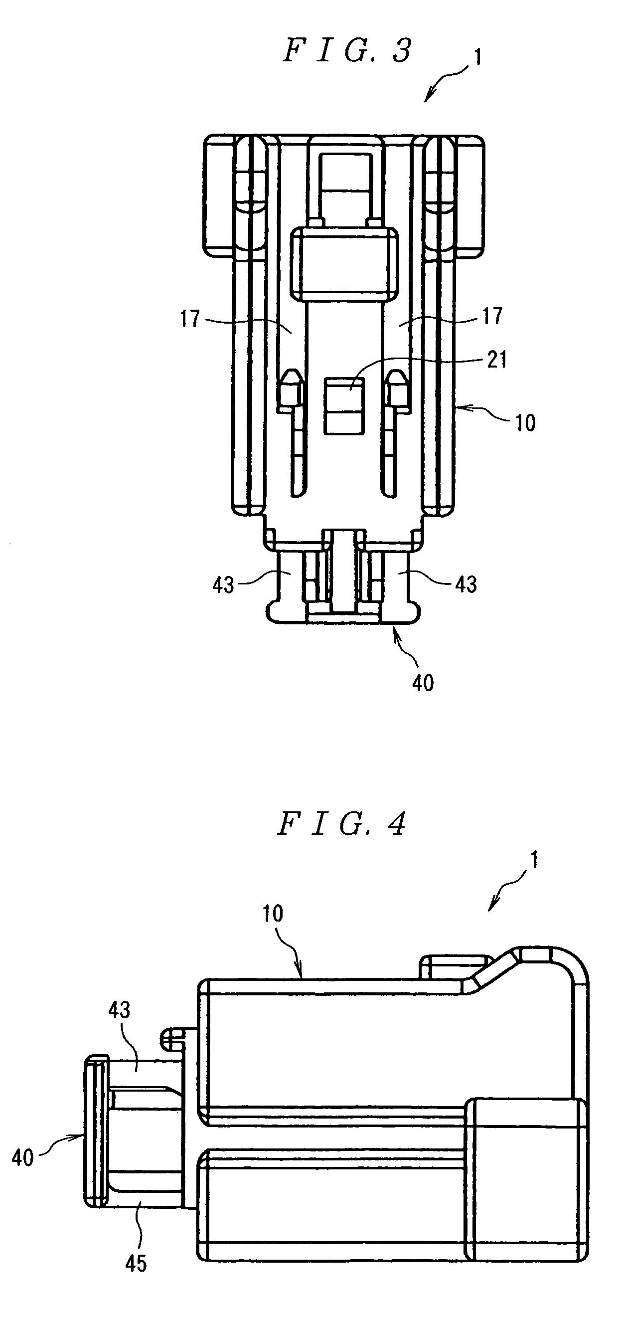
[0039]As shown in FIG. 3, a plurality of first locking openings 17 that extend in the forward-rearward direction in positions corresponding to the contact accommodating cavities 11 is formed in the top wall of the housing 10. As shown in FIG. 5A, the first locking opening 17 have inclined contact surfaces 17a. First retainer arm receiving openings 18 that communica...


PUM


Abstract

An electrical connector includes an insulating housing and a retainer. The housing has a plurality of contact accommodating cavities. The retainer is moveable between a temporary locking position and a main locking position. The retainer has first retainer arms that extend into a front surface of the housing. The first retainer arms have a second locking member formed on a top surface in a vicinity of a free end of the first retainer arms and a third locking member formed on a bottom surface in substantially a center of the first retainer arms. The second and third locking members are configured to abut the housing in the temporary locking position so that the retainer is prevented from moving from the temporary locking position to the main locking position.

Description

FIELD OF THE INVENTION[0001]The invention relates to an electrical connector having a housing and a retainer that is moveable from a temporary locking position to a main locking position within the housing.BACKGROUND OF THE INVENTION[0002]FIGS. 10, 11A, and 11B (Japanese Patent Application Kokai No. H9-161875) show a first conventional electrical connector 101. The electrical connector 101 includes an insulating housing 110. The housing 110 includes a contact accommodating member 111 having a plurality of contact accommodating cavities (not shown) for receiving contacts (not shown). A hood 112 extends forward from the contact accommodating member 111. Each of the contact accommodating cavities (not shown) has a first locking arm (not shown) for initially locking the contacts in the housing 110. A flexible second locking arm 113 extends forward from the contact accommodating member 111 and is disposed inside the hood 112 of the housing 110. The second locking arm 113 has a locking me...

Claims


Application Information

Patent Timeline
Patent Type & Authority Patents(United States)
IPC IPC(8): H01R13/436H01R13/42H01R13/627
CPCH01R13/4365H01R13/627
Inventor SAGAWA, TETSUYAKONO, TOSHIAKIYONEDA, TAKAHIROSAWADA, RYO
Owner TYCO ELECTRONICS JAPAN GK
Why Eureka
Try Eureka