Device for length and depth measurements in surgery

a technology for length and depth measurement and surgery, applied in the direction of instruments, prostheses, catheters, etc., can solve the problems of incorrect length measurement, irritation or damage to soft parts, incorrect length measurement, etc., and achieve good readability

Inactive Publication Date: 2006-11-14
SYNTHES USA
View PDF19 Cites 26 Cited by
  • Summary
  • Abstract
  • Description
  • Claims
  • Application Information

AI Technical Summary

Benefits of technology

[0008]In a preferred embodiment of the inventive device, the measuring sleeve and the measuring piston may comprise locking means. The locking means may hold the measuring piston in a selected position relative to the measuring sleeve, so that the device may be removed from the bone and the length measurement may be read outside of the surgical field. This allows for easy reading of the length measurement outside of the surgical field. The operating surgeon may freely hold the device such that neither light reflection off the device nor the style / font of the measurement markings affect the surgeon's measurement readings.
[0010]when the hook is extended, the measuring piston may be prevented from slipping off an opposite bone wall;
[0011]any unintentional movement of the measuring piston relative to the measuring sleeve may be prevented by a locking means, which may be disposed between the measuring piston and the measuring sleeve, and
[0012]the length measurement may not have to be read in situ and, thus, good readability may be achieved.

Problems solved by technology

However, the tip of the screw should not protrude excessively into the surrounding soft-tissue for this may result in irritation of or damage to the soft parts.
However, in so doing, the danger exists that the hook may slip off the opposite bone wall and, consequently, the displacement of the measuring sleeve may pull the hook into the bone.
This may result in incorrect length measurements and, consequently, may result in the selection of a bone screw of the incorrect length.

Method used


Image

  • Device for length and depth measurements in surgery
  • Device for length and depth measurements in surgery
  • Device for length and depth measurements in surgery

Examples


Embodiment Construction

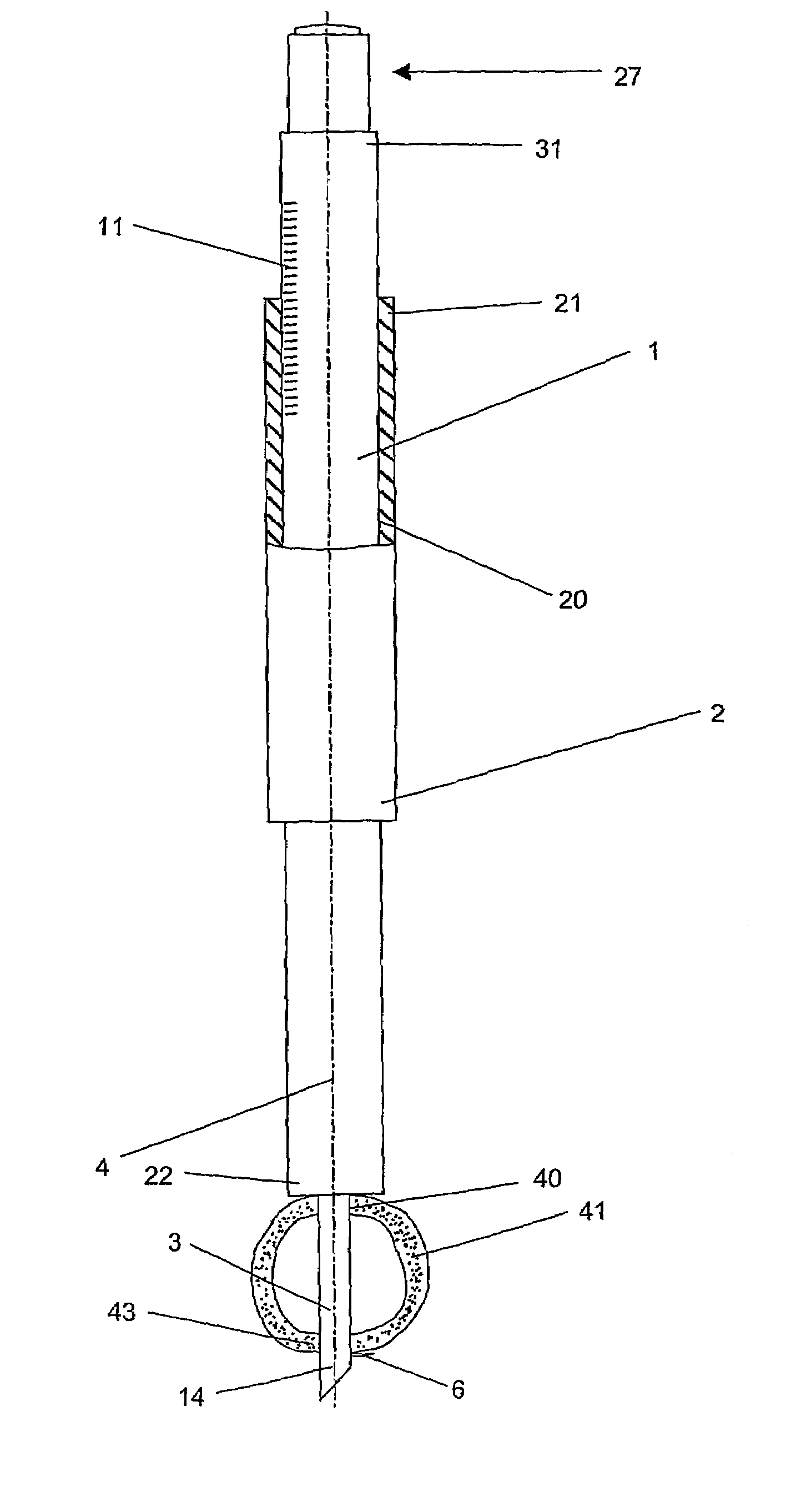
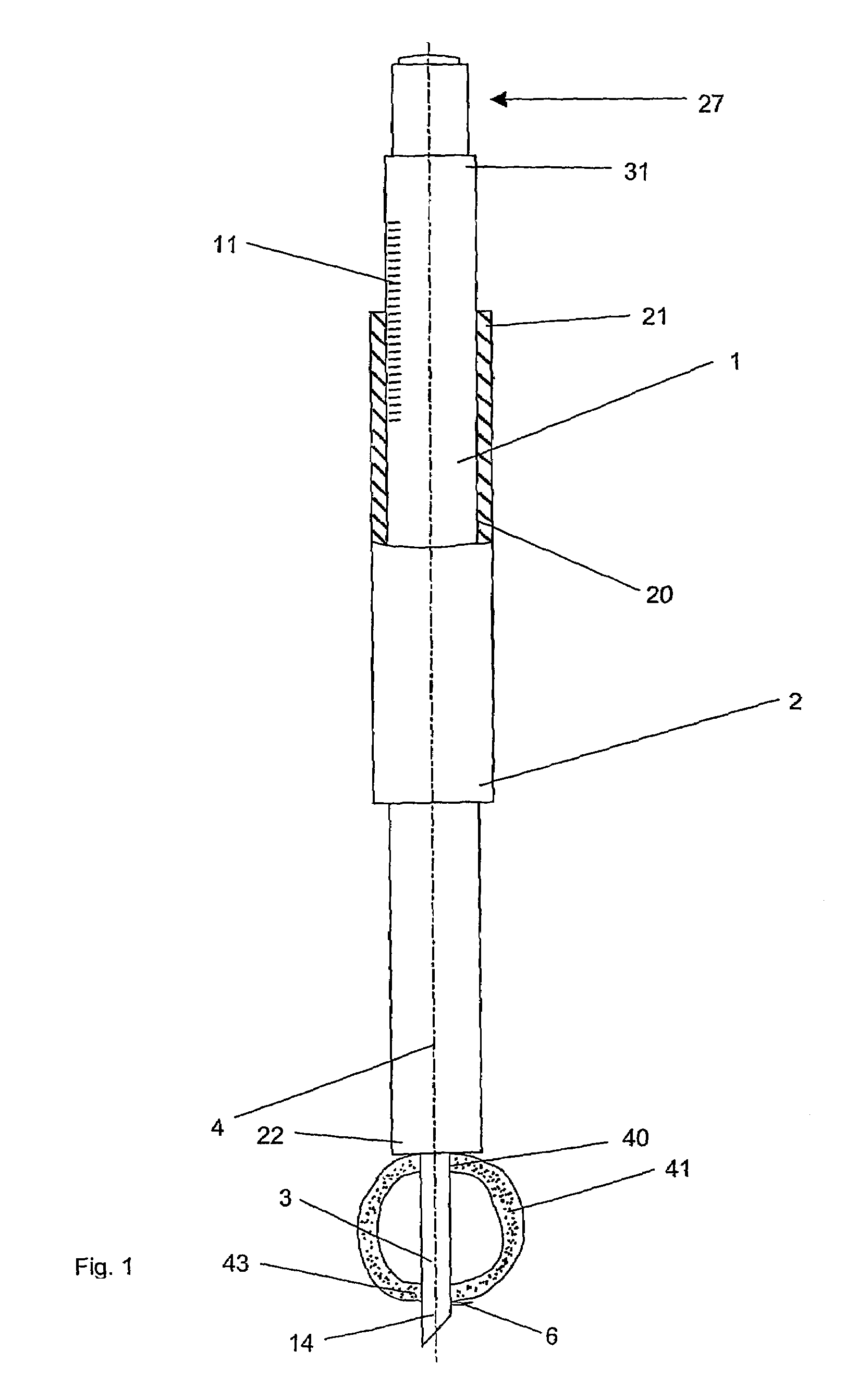
[0024]As shown in FIG. 1, the present invention comprises a first part 1 and a second part 2, the first 1 part may be constructed as a measuring piston and the second part 2 may be constructed as a measuring sleeve. It should, however, be understood that those of ordinary skill in the art will recognize many modifications and substitutions which may be made to various elements of the present invention.

[0025]The first part 1 may be moved parallel to the longitudinal axis 4 within a central borehole 20 in the second part 2. Depending on the position of the first part 1 relative to the second part 2, the tip 14 of the front part 3 of the first part 1 may protrude beyond the front end 22 of the second part 2. The front part 3 may be introduced into a borehole 40 in a bone 41, until the tip 14 protrudes beyond the bone portion 43 of the bone 41. The arresting means 27 may be disposed within the first part 1 so that it may be displaced parallel to the longitudinal axis 4. A hook 6 may be ...


PUM


Abstract

A device for taking length and depth measurements during surgery. The device comprises a first longitudinal member and a second longitudinal member telescopically positioned within the first longitudinal member. The second longitudinal member may have a front part connectable thereto. The front part may have an opening, a passageway, and a moveable piece in the passageway. The device may also have a sliding member for moving the moveable piece between a first position where a portion of the moveable piece is outside the front part to a second position where the entire moveable piece is within the front part. The first and second longitudinal member may be locked with respect to one another. The prevent invention also discloses methods of using the device to take length and depth measurements during surgery.

Description

CROSS REFERENCE TO RELATED APPLICATION[0001]The present application is a continuation of International Patent Application PCT / CH02 / 00071 filed Feb. 7, 2002, the entire content of which is expressly incorporated herein by reference thereto.FIELD OF THE INVENTION[0002]The invention relates to a device for length and depth measurements in surgery and, in particular, a device for positioning through a borehole in a bone to measure the distance from one side of the bone to the other side of the bone.BACKGROUND OF THE INVENTION[0003]Bone screws are commonly used in osteosynthetic repair of, for example, bone fractures. Frequently, bone screws are screwed into a bone perpendicular to its longitudinal axis. In so doing, the bone screws may penetrate into an opposite bone wall. However, the tip of the screw should not protrude excessively into the surrounding soft-tissue for this may result in irritation of or damage to the soft parts. An accurate determination of length of the borehole is t...

Claims


Application Information

Patent Timeline
Patent Type & Authority Patents(United States)
IPC IPC(8): A61B1/00A61F5/04A61B17/58A61B5/107A61B19/00
CPCA61B5/1072A61B5/1076A61B19/46A61B5/4504A61B2019/461A61B90/06A61B2090/061
Inventor RUPP, STEPHANPELTZER, JORG
Owner SYNTHES USA
Why Eureka
Try Eureka