Device for radiation therapy under image monitoring

Inactive Publication Date: 2009-05-14
SIEMENS HEALTHCARE GMBH
View PDF26 Cites 26 Cited by
  • Summary
  • Abstract
  • Description
  • Claims
  • Application Information

AI Technical Summary

Benefits of technology

[0013]In particular, the static design of the exposure device allows a significant reduction of the volume required for said device. Moreover, a static exposure device is technically less complicated and therefore easier and cheaper to realize. At the same time, the quality of the exposure is thereby not negatively influenced by the possibility of a rotation of the examination subject, and an applied radiation dose outside of the target volume can furthermore be minimized, healthy tissue can thus be protected.
[0014]The pa

Problems solved by technology

However, in the exposure the problem frequently arises that the target of the exposure in the body is mobile.
Moreover, a tumor can also shift, grow or already shrink in the time period between the exposure planning and the actual exposure.
These known combinations have the disadvantage that the image quality of x-ray-based imaging techniques is not optimal for the de

Method used


Image

  • Device for radiation therapy under image monitoring
  • Device for radiation therapy under image monitoring
  • Device for radiation therapy under image monitoring

Examples


first embodiment

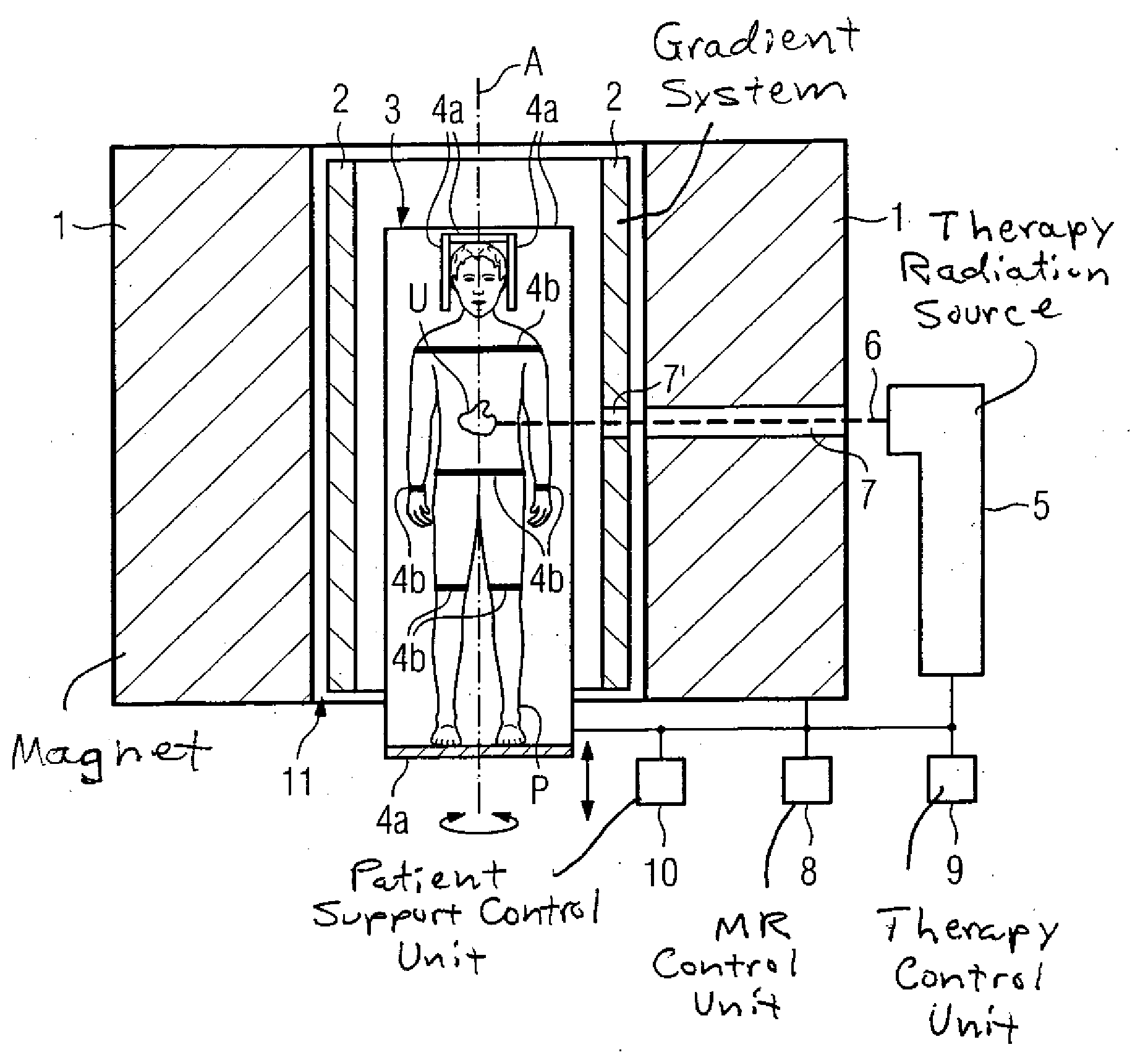
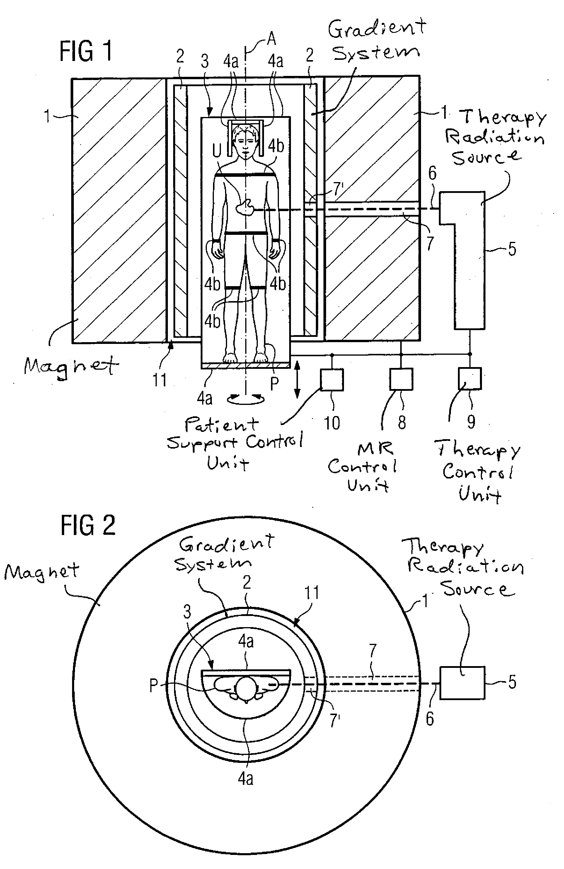
[0021]FIGS. 1 and 2 show (in longitudinal section and in plan view, respectively) a schematic representation of the invention for radiation therapy under image monitoring that has a magnetic resonance device and an exposure device. Image data of an examination subject U are generated with the magnetic resonance device, and in particular position and dimensions of the examination subject are monitored.

[0022]Only one magnet 1 and one gradient system 2 and, schematically, one control unit 8 of the magnetic resonance device are shown. Additional components of the magnetic resonance device such as radio-frequency antennas for radiation of excitation pulses and for acquisition of signals, display and image processing units and their cooperation are well known and therefore need not be shown nor described in detail herein.

[0023]The exposure device is also only schematically represented by a radiation source 5 and a control unit 9. A linear accelerator is advantageously used as an exposure ...

second embodiment

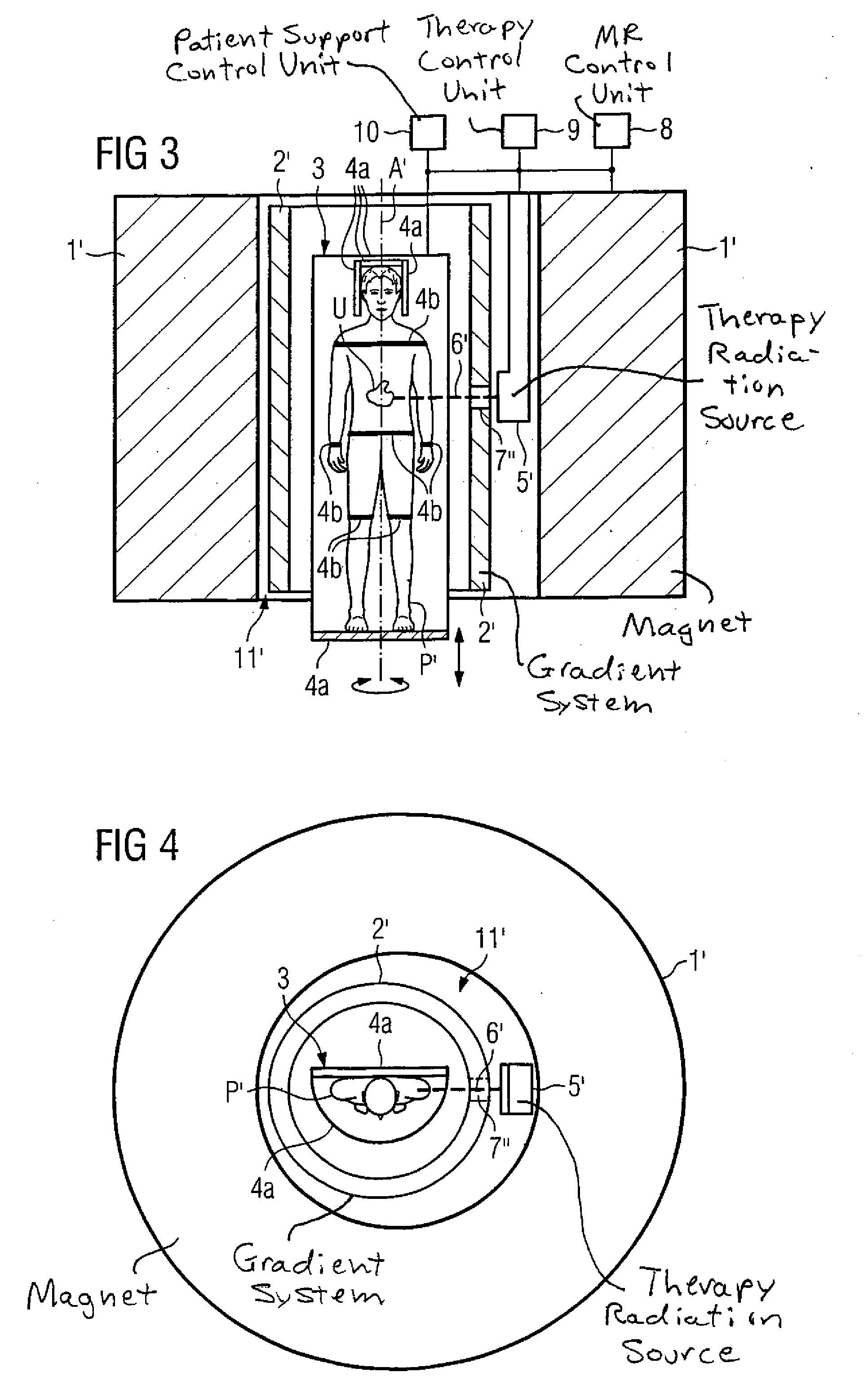
[0043]In this second embodiment, the therapy beam 6′ does not need to penetrate through the magnet 1′, rather only through the gradient system 2′. For this purpose, the gradient system 2′ has a radiation-permeable area 7″. The statements on the specification of FIGS. 1 and 2 is likewise referenced with regard to design possibilities of this radiation-permeable area 7″.

[0044]FIGS. 5 and 6 show (again in a longitudinal section or in plan view) a schematic representation of a third embodiment of a device for radiation therapy under image monitoring, which third embodiment comprises a magnetic resonance device and an exposure device. Image data of an examination object U are generated with the magnetic resonance device, and in particular position and dimensions of the examination subject are monitored.

[0045]Again, only one magnet 1″ and one control unit 8 are of the magnetic resonance device schematically shown. Additional components of the magnetic resonance device—for example a gradie...


PUM


Abstract

A device for radiation therapy implemented with image monitoring has a magnetic resonance device and an exposure device. The magnetic resonance device has a magnet and primarily serves for image monitoring an examination object of a patient in an examination volume of the magnetic resonance device. The exposure is fashioned to be static and serves to expose the examination subject in the examination volume with therapeutic beams. The patient (and therefore the examination subject) are supported by a patient positioning device such that the examination subject can be moved relative to the magnetic resonance device and the exposure device around at least one rotation axis.

Description

BACKGROUND OF THE INVENTION[0001]1. Field of the Invention[0002]The present invention concerns a device for radiation therapy implemented with image monitoring.[0003]2. Description of the Prior Art[0004]In the framework of radiation therapy, in general a target within the human body should be irradiated in order to combat illnesses, in particular cancer. A high radiation dose is generated specifically in an exposure center (isocenter) of an exposure device. In order to minimize the radiation dose outside of the target volume and thus to protect healthy tissue, the entire radiation generator is normally moved around the static patient. The radiation dose is thereby concentrated in the beam in the region of the rotation axis.[0005]However, in the exposure the problem frequently arises that the target of the exposure in the body is mobile. For example, a tumor in the abdominal region shifts during the breathing cycle. Moreover, a tumor can also shift, grow or already shrink in the time...

Claims


Application Information

Patent Timeline
IPC IPC(8): A61N5/10A61B5/055
CPCA61B5/0555A61B6/0457G01R33/4808A61N2005/1055A61N5/1049A61B5/055A61B6/0487
Inventor ROELL, STEFANSCHMIDT, SEBASTIANSIEBERT, ANKE
Owner SIEMENS HEALTHCARE GMBH
Why Eureka
Try Eureka