Hybrid antenna and integrated proximity sensor using a shared conductive structure

a proximity sensor and hybrid antenna technology, applied in the field of wireless communication, can solve problems such as detection failures, and achieve the effects of saving cost, reducing volume required, and efficient method of maintaining antenna performan

Inactive Publication Date: 2016-06-16
KYOCERA AVX COMPONENTS (SAN DIEGO) INC
View PDF3 Cites 2 Cited by
  • Summary
  • Abstract
  • Description
  • Claims
  • Application Information

AI Technical Summary

Benefits of technology

[0008]A proximity sensor can be positioned beside or beneath an antenna and the antenna can be re-tuned to compensate for the effect of placing the metal conductors near the antenna. A more efficient method in terms of maintaining antenna performance, reducing volume required, and saving cost is to design the proximity sensor into the antenna structure. This combination antenna and proximity sensor will provide a more optimized and cost effective solution for devices that require antennas and proximity sensing systems. More importantly, by designing the proximity sensor, or multiple proximity sensors into the antenna, the ability to detect changes to the environment in the region of the antenna can be improved. This is important, since it is desirable to know when objects are positioned close to the antenna. Sensing when objects are in close proximity to an antenna can assist in re-tuning the antenna and keeping the antenna impedance optimized.

Problems solved by technology

With this traditional two-sensor architecture there is a possibility that the detection is missed, for example, where the object is in between the two sensor pads.

Method used


Image

  • Hybrid antenna and integrated proximity sensor using a shared conductive structure
  • Hybrid antenna and integrated proximity sensor using a shared conductive structure
  • Hybrid antenna and integrated proximity sensor using a shared conductive structure

Examples


Embodiment Construction

[0016]In the following description, for purposes of explanation and not limitation, details and descriptions are set forth in order to provide a thorough understanding of the embodiments of the invention. However, it will be apparent to those skilled in the art that the present invention may be practiced in other embodiments, including certain variations or alternative combinations that depart from these details and descriptions. The following description is provided in order to enable those having skill in the art to make and use the preferred embodiment(s) of the invention.

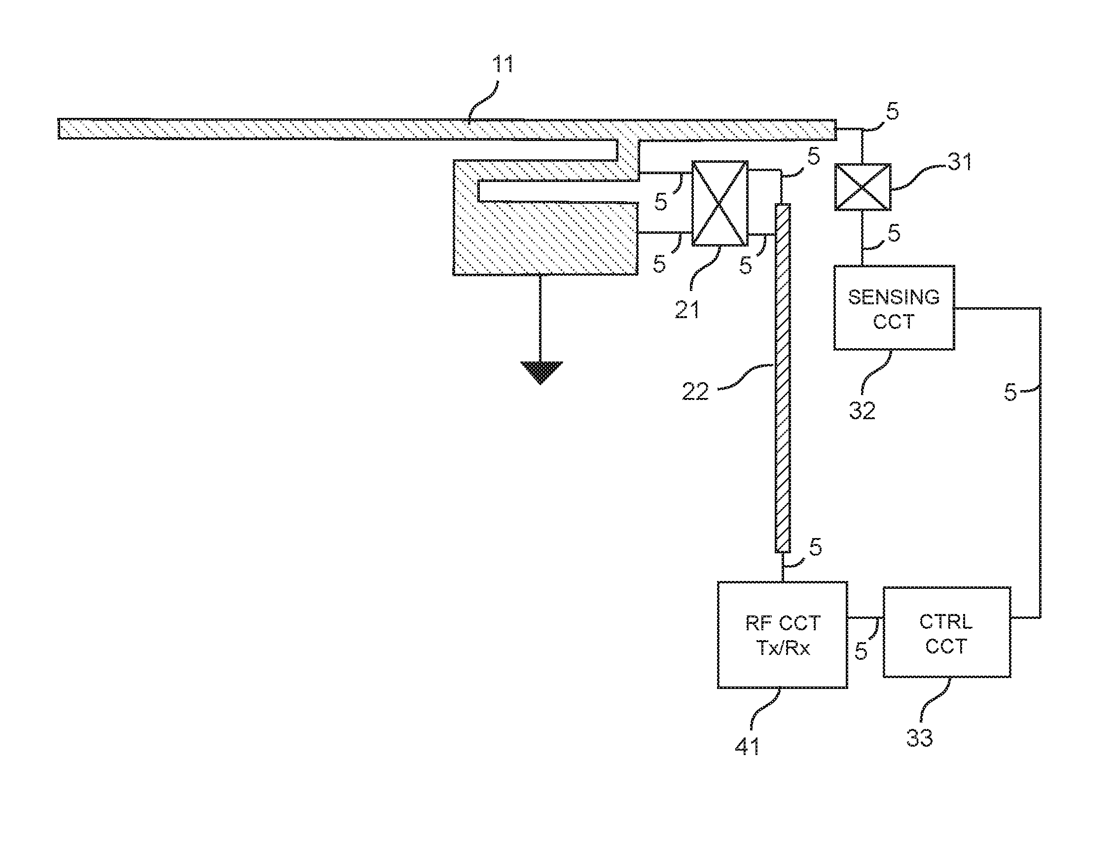
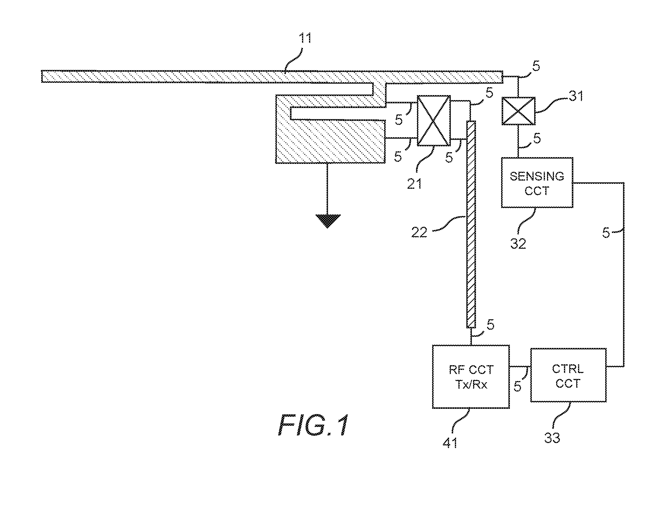
[0017]Now turning to the drawings, FIG. 1 shows a hybrid antenna and sensing component in accordance with an embodiment. The hybrid antenna and sensing component comprises an elongated conductor 11 coupled to a transceiver circuit 41 via a coaxial cable 22 extending therebetween. A first filter 21 is positioned between the elongated conductor 11 and the transceiver 41. The first filter 21 may include: a high pas...


PUM


Abstract

A hybrid antenna and integrated proximity sensor is described wherein a commonly shared conductive structure is used for both antenna functions as well as a proximity sensor functions.

Description

CROSS-REFERENCE TO RELATED APPLICATIONS[0001]This application claims benefit of priority with U.S. Provisional Ser. No. 62 / 090,887, filed Dec. 12, 2014; the contents of which are hereby incorporated by reference.BACKGROUND[0002]1. Field of the Invention[0003]This invention relates generally to the field of wireless communication; and more particularly, to wireless communication networks and antenna array techniques for interference suppression and multipath mitigation.[0004]2. Description of the Related Art[0005]Proximity sensors are in use today in commercial wireless devices as well as other product groups, and are used for a wide variety of applications. For example, it is common for a proximity sensor to be integrated into a cell phone, with the proximity sensor used to sense when the display region of the cell phone is in close proximity to an object. This sensing of an object being close to the display is used to reduce battery power consumption by turning off or down the brig...

Claims


Application Information

Patent Timeline
Patent Type & Authority Applications(United States)
IPC IPC(8): H01Q1/52H01Q1/24
CPCH01Q1/243H01Q1/44H01Q9/42
Inventor HENG, CHEW CHWEE
Owner KYOCERA AVX COMPONENTS (SAN DIEGO) INC
Why Eureka
Try Eureka