Developing device having movable coupling member for engagement to electrophotographic image forming apparatus

a technology of developing device and developing roller, which is applied in the direction of yielding coupling, electrographic process apparatus, instruments, etc., can solve the problem of difficult to prevent uneven rotation of developing roller

Active Publication Date: 2014-10-28
CANON KK
View PDF40 Cites 25 Cited by
  • Summary
  • Abstract
  • Description
  • Claims
  • Application Information

AI Technical Summary

Benefits of technology

[0012]A further object of the present invention is to maintain a coupling member at a pre-engagement angular position (second angular position) even in the case where the developing cartridge is in a free state. Therefore, the coupling member is prevented from unintentional movement in transporting the developing cartridge, for example.
[0020]A further object of the present invention is to provide a developing device (developing cartridge), wherein the developing roller is rotated smoothly as compared with the case in which a driving connection between the main assembly, and the developing device (developing cartridge) is carried out by the gear-to-gear transmission.
[0023]A further object of the present invention is to provide a developing device (developing cartridge), wherein the developing roller which can be engaged with the drive shaft in the direction substantially perpendicular to the axial direction of the drive shaft provided in the main assembly is rotated smoothly.
[0029]A further object of the present invention is to provide the developing device (developing cartridge) which is engaged and disengaged in the direction substantially perpendicular to the axial direction of the drive shaft relative to the drive shaft provided in the main assembly by the movement (rotation) of a movable member (rotary member) and which rotates the developing roller smoothly.
[0039]A further object of the present invention is to provide a developing device (developing cartridge), wherein even in such a case, the engagement and disengagement relative to the drive shaft are assured, and the developing roller is rotated smoothly.

Problems solved by technology

For this reason, it is difficult to prevent a rotation unevenness of the developing roller.

Method used


Image

  • Developing device having movable coupling member for engagement to electrophotographic image forming apparatus
  • Developing device having movable coupling member for engagement to electrophotographic image forming apparatus
  • Developing device having movable coupling member for engagement to electrophotographic image forming apparatus

Examples


Embodiment Construction

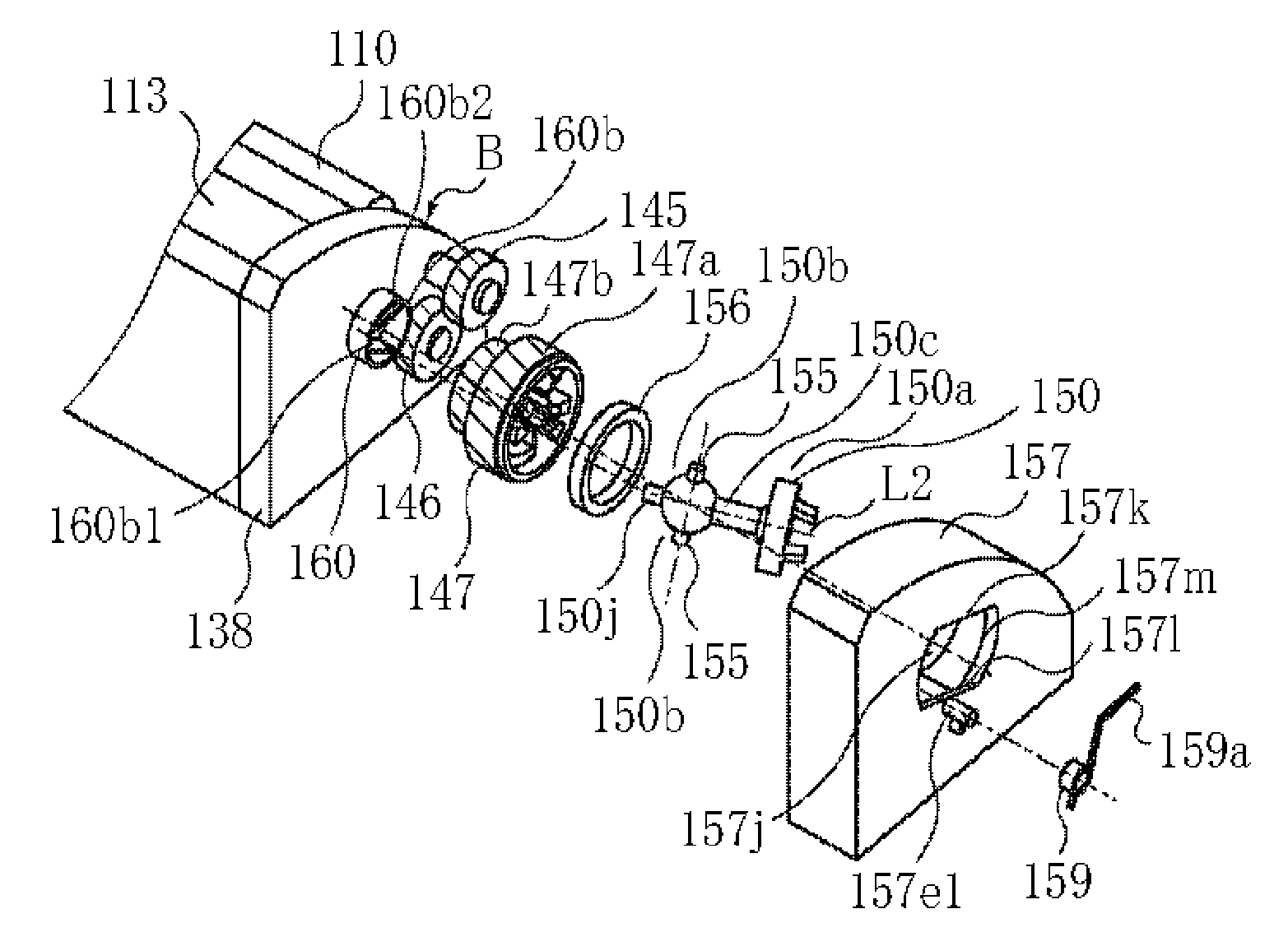
[0085]The preferred embodiments of the present invention will be described in conjunction with the accompanying drawings First a coupling member (rotational force transmitting part) according to an embodiment of the present invention will be described.

[0086]The present invention relates to a developing cartridge (FIG. 2, for example), and an electrophotographic image forming apparatus (FIG. 4, for example) itself. In addition, the present invention is applicable to a coupling member (rotational force transmitting part) (FIG. 7A-7F, for example, FIG. 31) itself.

(1) Developing Cartridge

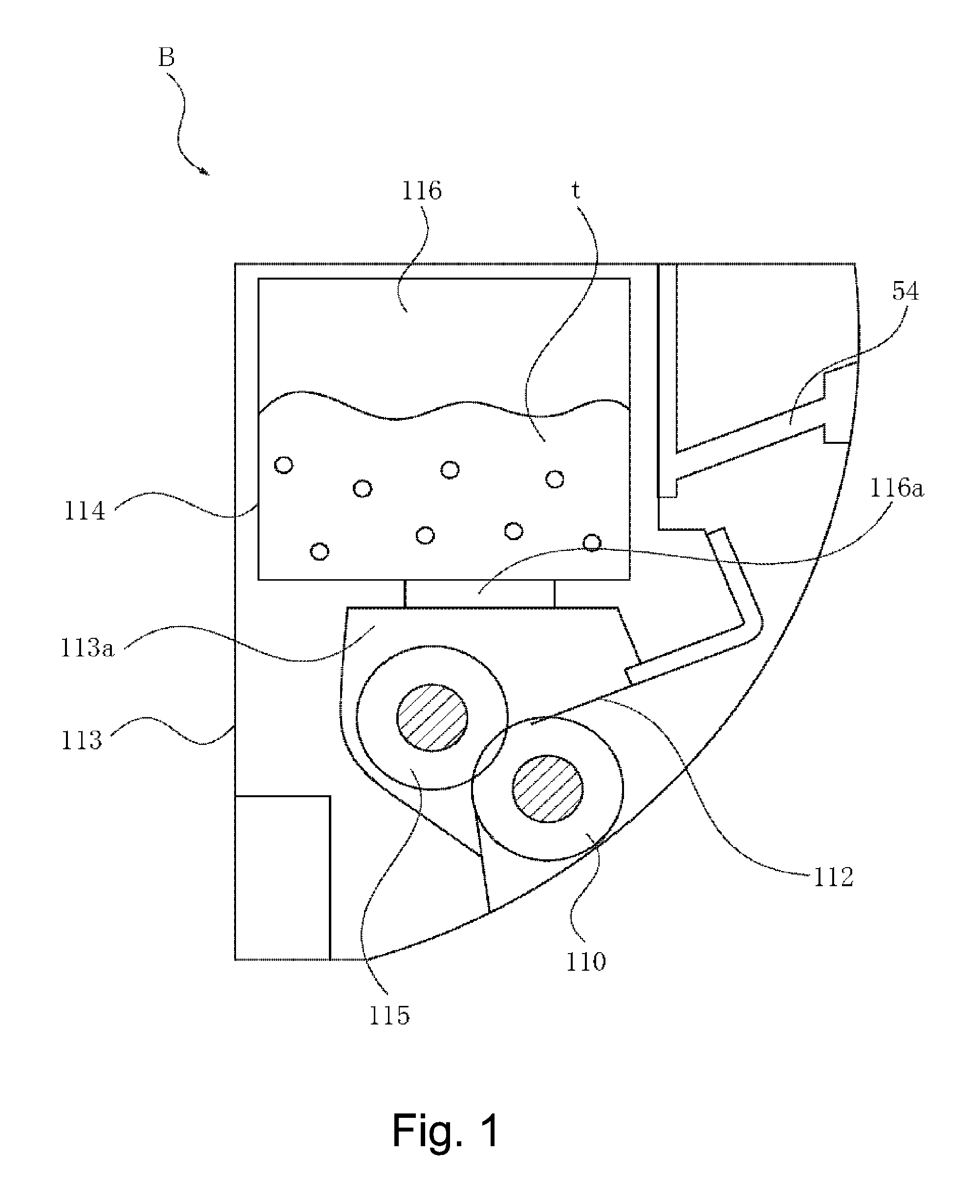
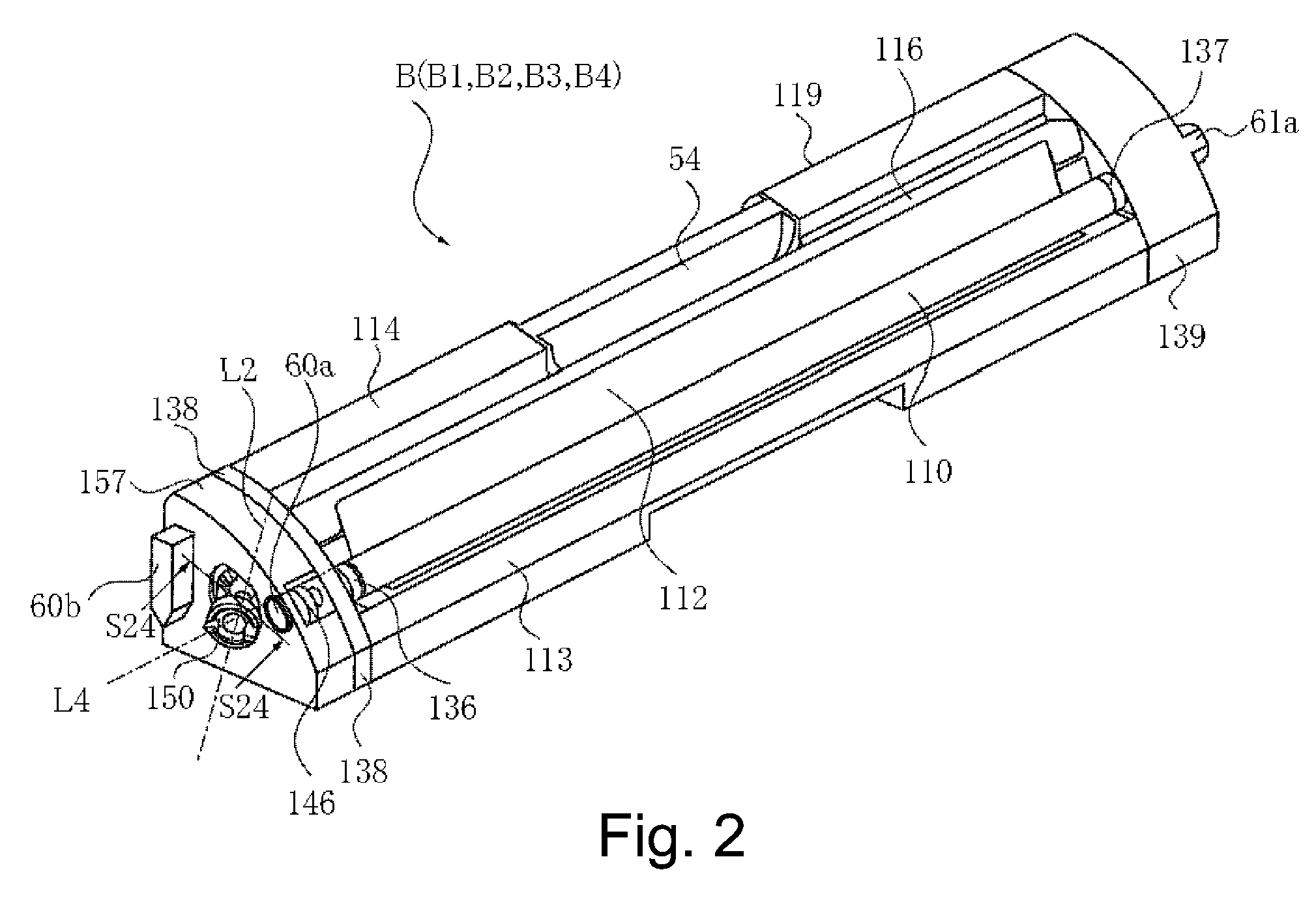
[0087]Referring to FIG. 1-FIG. 4, a developing cartridge B as the developing device (cartridge) according to an embodiment of the present invention will be described. FIG. 1 is a sectional view of a cartridge B. The FIGS. 2 and 3 are perspective views of the cartridge B. FIG. 4 is a sectional view of color electrophotographic image forming apparatus main assembly A (main assembly).

[0088]The cartridge B ...


PUM


Abstract

A developing device is usable with an electrophotographic image forming apparatus including a shaft and a rotary unit mounting the device. When mounted, the device is movable perpendicular to a shaft axial direction in response to movement of the rotary unit and the shaft is not movable in that direction. The device includes a developing roller that contacts and separates from a drum in response to movement of the rotary unit, and a coupler transmitting a rotating force to the roller. The coupler includes a portion engaging the shaft to receive a rotating force and a portion transmitting the received rotating force to the roller. The coupler takes a first position for transmitting the rotational force to the roller, a position before the coupler engages the shaft and is inclined away from the first position, and a position for the disengagement of the coupler and the shaft.

Description

FIELD OF THE INVENTION AND RELATED ART[0001]The present invention relates to a developing device, a developing cartridge, a rotational force transmitting part, and an electrophotographic image forming apparatus with which the developing cartridge is used.[0002]The electrophotographic image forming apparatus forms an image on a recording material using an electrophotographic image forming process. The electrophotographic image forming apparatus includes an electrophotographic copying machine, an electrophotographic printer (a laser beam printer, an LED printer), and so on.[0003]In addition, the developing cartridge is dismountably mounted to a main assembly of the electrophotographic image forming apparatus, and develops an electrostatic latent image formed on the electrophotographic photosensitive member. By a user exchanging the developing cartridge, a maintenance operation of the image forming apparatus is carried out in effect.[0004]Conventionally, in the electrophotographic imag...

Claims


Application Information

Patent Timeline
Patent Type & Authority Patents(United States)
IPC IPC(8): G03G15/01F16D1/10G03G15/04F16D3/205
CPCF16D1/10G03G2215/0177G03G15/0152F16D3/2052G03G15/0173G03G15/0121G03G2221/1657G03G21/1857G03G15/01G03G15/14G03G21/00
Inventor TAKASAKA, ATSUSHIMIYABE, SHIGEOUENO, TAKAHITO
Owner CANON KK
Why Eureka
Try Eureka