Lift Assist

a technology of lift assist and gas spring, which is applied in the direction of storage devices, applications, furniture parts, etc., can solve the problems of no longer being able to open the luggage bin to remove the luggage inside, and the valve of the gas spring acting, and achieve the effect of compact size and small current consumption

Active Publication Date: 2014-09-04
GENERAL AEROSPACE
View PDF10 Cites 26 Cited by
  • Summary
  • Abstract
  • Description
  • Claims
  • Application Information

AI Technical Summary

Benefits of technology

[0018]It is advantageous if at least one leg in or near the dead center position of the toggle can be positioned with respect to at least one stop spaced apart from the knee joint axis and if the actuation mechanism has at least one first return element by means of which this leg can be pressed against the stop. This can even more reliably prevent an unintentional movement of the toggle and thus of the first locking element in the event of acceleration forces or vibrations.
[0019]In one practical embodiment of the invention, the first locking element is connected to the toggle by way of an operating lever. The operating lever is connected with the base section so as to pivot about a pivot axis; the operating lever can be supported on one support point spaced apart from the pivot axis with respect to the first locking element and is connected to the first leg of the toggle so it can pivot about a first joint axis spaced apart from the support point and from the pivot axis, and running parallel to the pivot axis. The second leg is connected to the base section so it can pivot about another joint axis located in parallel with the pivot axis. In this way, the power assist device allows a narrow structural shape in which the toggle can be located on the base section in the space along a straight-line extension of the spring.
[0020]In a preferred embodiment of the invention, the actuation mechanism has an electromagnet with an electromagnetically moving actuation element by means of which the toggle can be moved from the locked position into the activation position in which the actuation element can be pushed between a position of rest and a working position perpendicular to the knee joint axis. In this embodiment, the electromagnet serves as an inexpensive electric drive for moving the operating stage of the actuation mechanism.
[0021]In a refinement of the invention, the actuation element is designed as a striker that, in the position of rest, is spaced apart by a free space from an actuation point of the toggle that is at a distance from the joint axis and that, in the working position, is positioned against the actuation point. For changing the operating state of the actuation mechanism, the actuation element, in its position of rest, can be accelerated by the magnetic force of the electromagnet into the free space such that it has kinetic energy when it contacts the toggle and this energy is sufficient to move the toggle. Under these circumstances, the electromagnet can be of an appropriately small size so that it only has a small current consumption.
[0022]Advantageous is the case that, if the spring is designed as a helical spring and if a hydraulic damping mechanism is located within the helical spring and this damping mechanism has at least one piston located so that it can be pushed into an operating cylinder, and if the support element is connected to the first and / or second abutment point by way of the damping mechanism. The motion of the support element and the shell, which is connected to it, is damped by the damping mechanism and still allows the power assist device to be of a very compact size because the damping mechanism is accommodated within the helical spring.

Problems solved by technology

The previously known power assist device, however, has the disadvantage that, in the event of a fault in the electronic control system and / or in the touch sensor, it may occur that the valve of the gas spring actuates when the luggage shell is not in the open position.
In this case, the luggage shell is blocked in the position in question, a situation that may result in it no longer being possible to open the luggage bin to remove the luggage inside.

Method used


Image

  • Lift Assist
  • Lift Assist
  • Lift Assist

Examples


Embodiment Construction

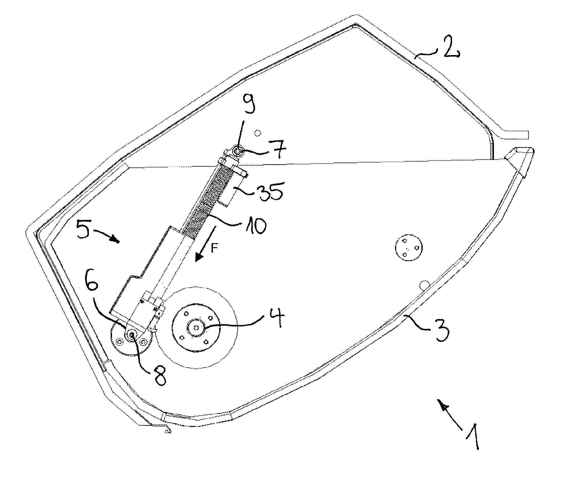
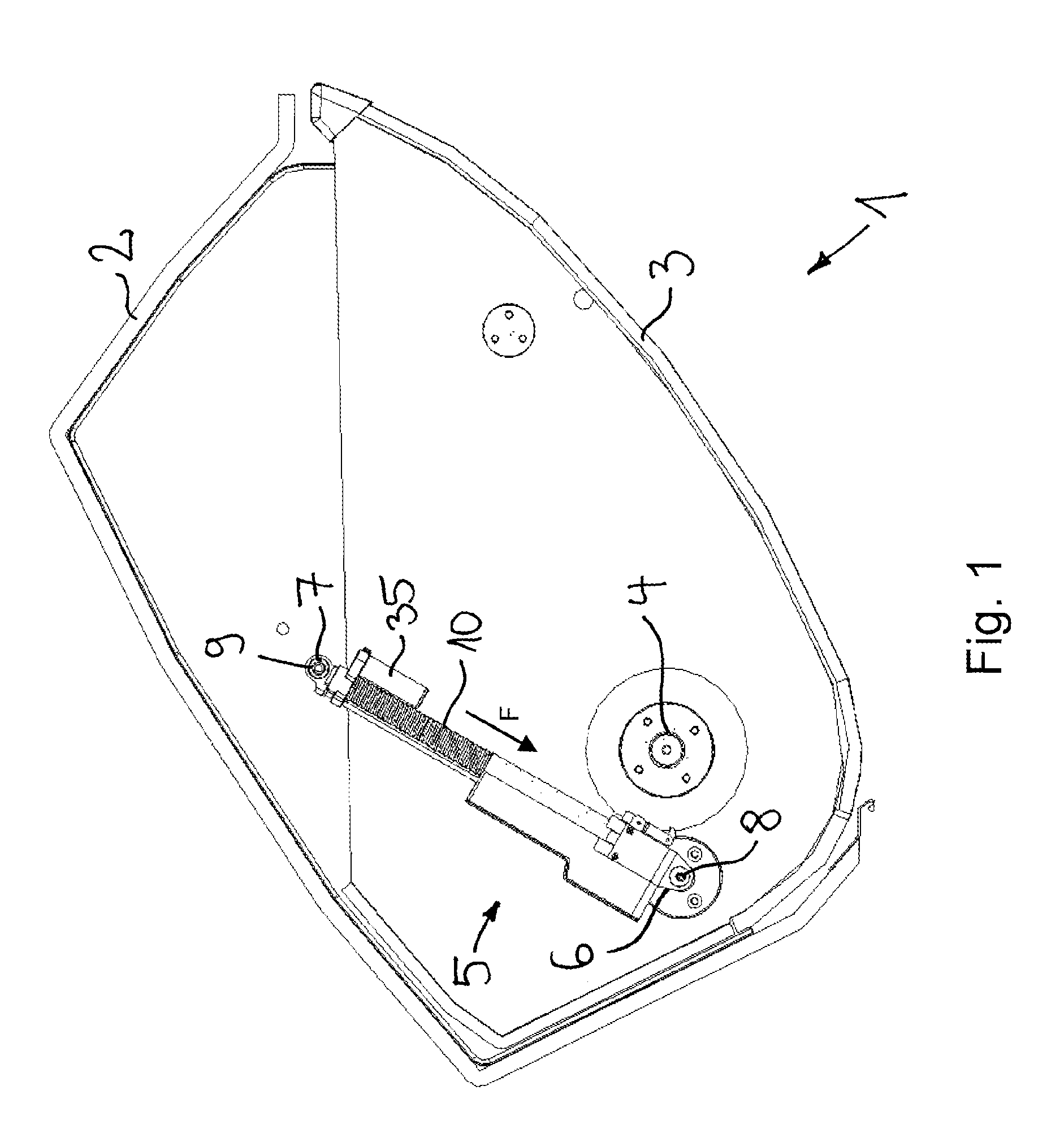
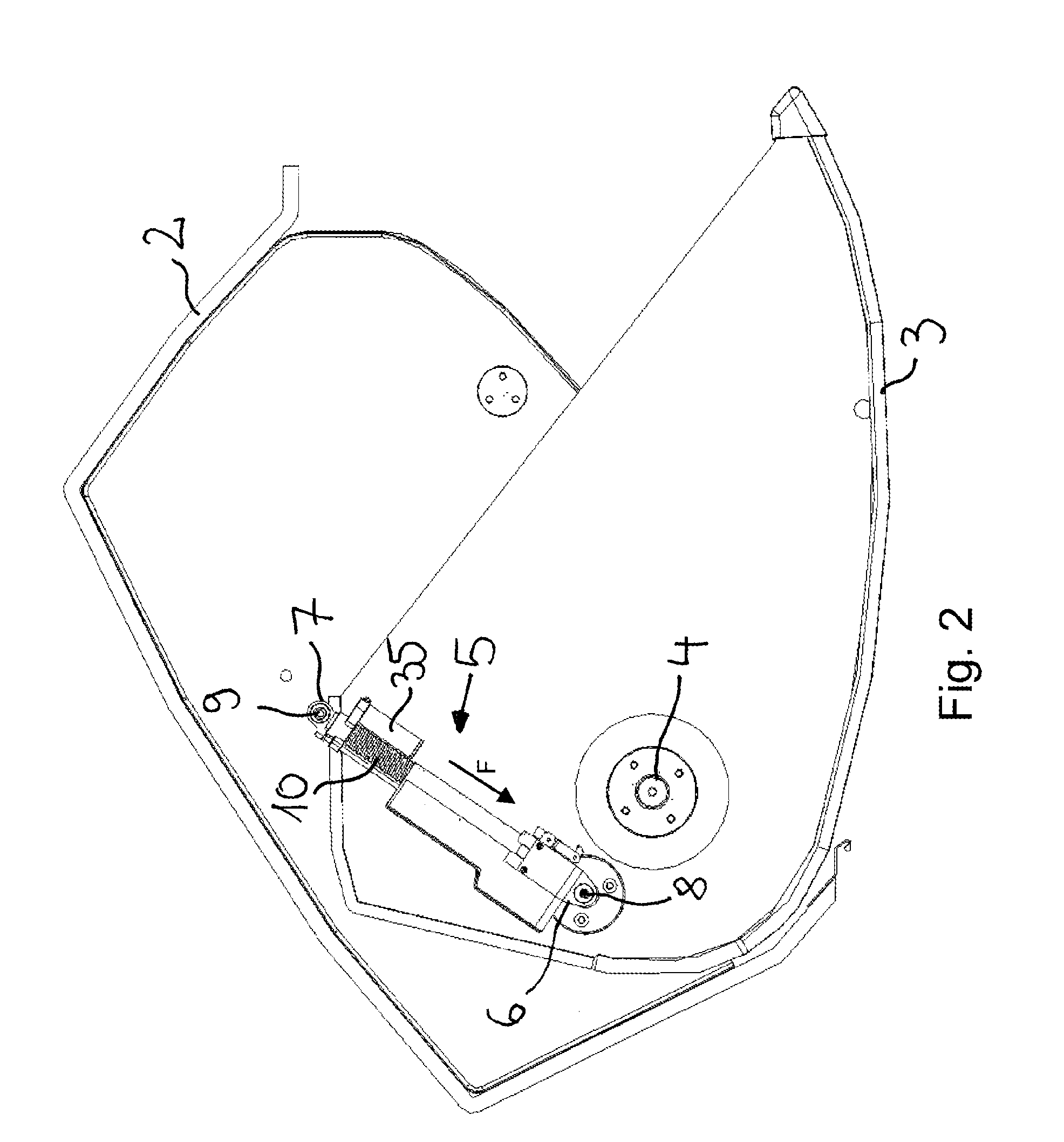
[0040]A luggage bin, identified in its entirety with 1, in a passenger compartment of a passenger airplane has a housing 2 to which a drop-down shell 3, which serves to accommodate pieces of luggage, is attached. The shell 3 can be pivoted about a roughly horizontal, notional axis by means of thrust bearings 4, connected to the housing 2 and can be pivoted in a closed position (FIG. 1) and an open position (FIG. 2) relative to the housing 2. In the closed position, the shell 3 can be locked to the housing 2 by means of a locking mechanism not shown in more detail in the drawing.

[0041]The thrust bearings 4 are located on the shell 3 such that, when the shell 3 is loaded with luggage, the center of gravity of the shell 3 and that of the luggage contained therein are spaced apart in the horizontal direction from the axis of the thrust bearings 4 so that a torque acts on the shell 3 and this torque pivots the shell 3 downward.

[0042]So that the luggage shell, when loaded, can still easil...


PUM


Abstract

A power assist device for use in a luggage bin with a drop-down shell has a load measuring mechanism, a power assist mechanism, and an actuation mechanism. The load measuring mechanism is changed from the inactive operating state to the active operating state by the actuation mechanism when the load determined by the load measuring mechanism exceeds a specified threshold that is larger than an assist force. The actuation mechanism has cooperating locking elements of which a first element is connected to a first abutment point and a second element is connected to a second abutment point. The locking elements can move relative to one another such that, in an inactive operating state, the one locking element meshes with a friction fit into the cooperating other locking element and releases it in an active operating state.

Description

CROSS-REFERENCE TO RELATED APPLICATION[0001]This application claims priority to German Patent Application No. 10 2013 003 364.0 filed Mar. 1, 2013, the disclosure of which is hereby incorporated in its entirety by reference.BACKGROUND OF THE INVENTION[0002]1. Field of the Invention[0003]The invention relates to a power assist device for use in a luggage bin with a drop-down shell, in particular in a passenger aircraft with[0004]a load measuring mechanism for determining the load acting on the drop-down shell of the luggage bin;[0005]a power assist mechanism to apply an assist force to the shell counteracting the load where the power support mechanism has a mechanical spring whose end areas can move in an actuation direction toward one another against the return force of the spring from a first position into a second position and where a first end area of the spring can be supported by way of a first abutment point on a base section and a second end area of the spring can be supporte...

Claims


Application Information

Patent Timeline
Patent Type & Authority Applications(United States)
IPC IPC(8): B64D11/00
CPCB64D11/003E05Y2201/21
Inventor GENG, JOHANNES
Owner GENERAL AEROSPACE
Why Eureka
Try Eureka