

Light diffusing plate, liquid crystal display apparatus and rear projection apparatus
- Summary
- Abstract
- Description
- Claims
- Application Information
AI Technical Summary
Benefits of technology
Problems solved by technology
Method used
Image

Examples
second embodiment
[0102]In the above-described embodiment, the light exit areas 44 are circular whereas the light diffusing plate according to the present invention has rectangular light exit areas.
[0103]In this light diffusing plate, if the length of one side of the rectangular light exit area is written as A, the length of another side of the rectangular light exit area as B, the size of the microlens in a direction corresponding to the side having the above-described length A as Sa, the size of the microlens in a direction corresponding to the side having the above-described length B as Sb, other factors than the above-described factors are the same as in the previous embodiment, the following relations are satisfied:
Sa≧2t×tan θ+A; and
Sb≧2t×tan θ+B
[0104]Also in this embodiment, the center (intersection point of diagonal lines of the rectangle) of the rectangular light exit area is set on-axis or in alignment with the optical axis of the corresponding microlens.
[0105]Further, the sizes Sa and Sb o...
third embodiment
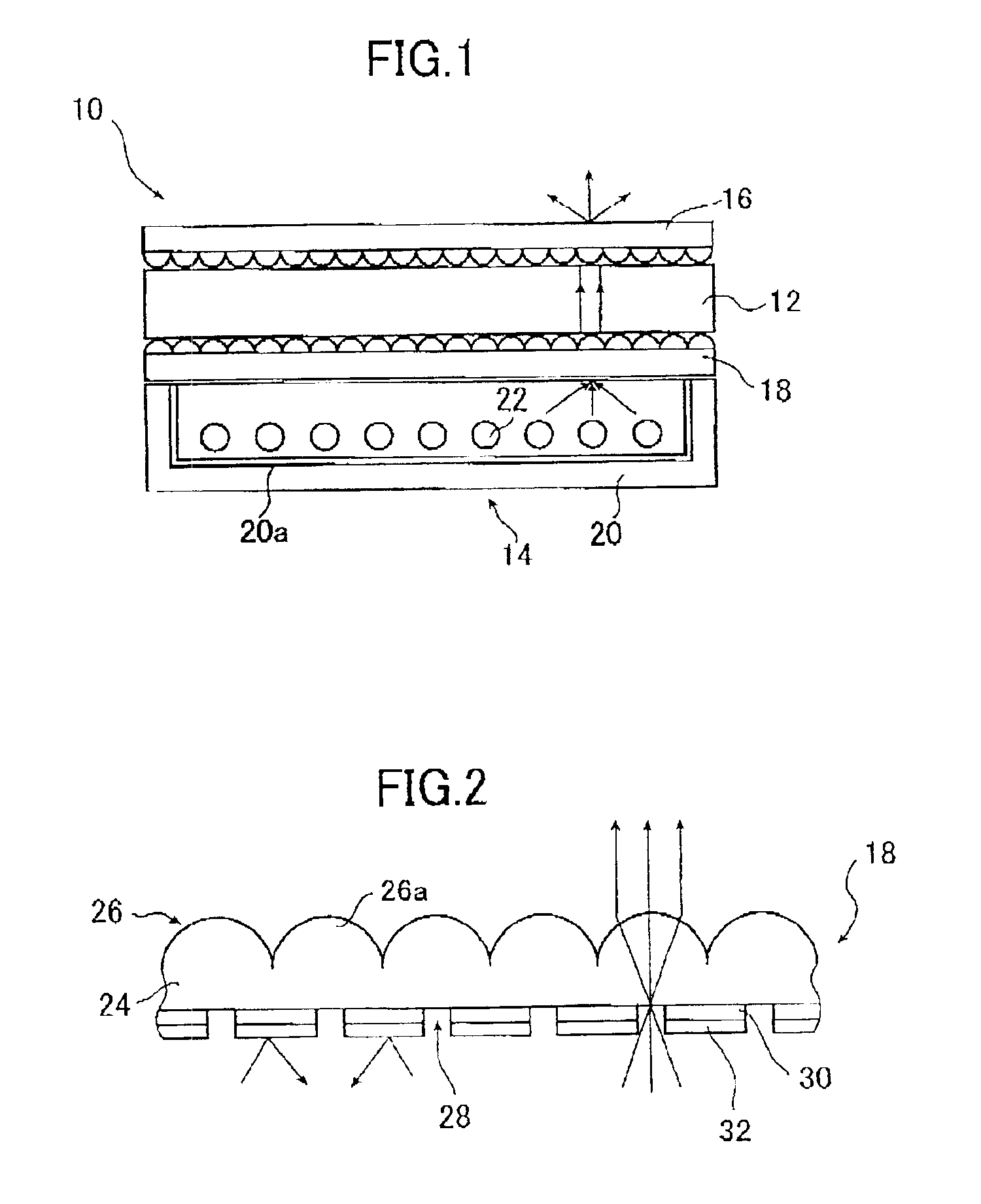
[0117]On this occasion, in the display apparatus 10 according to the present invention, as the light diffusing plate 16, a light diffusing plate 17 according to the present invention can be used.
[0118]FIG. 11A schematically shows the light diffusing plate 17 according to the third embodiment of the present invention.
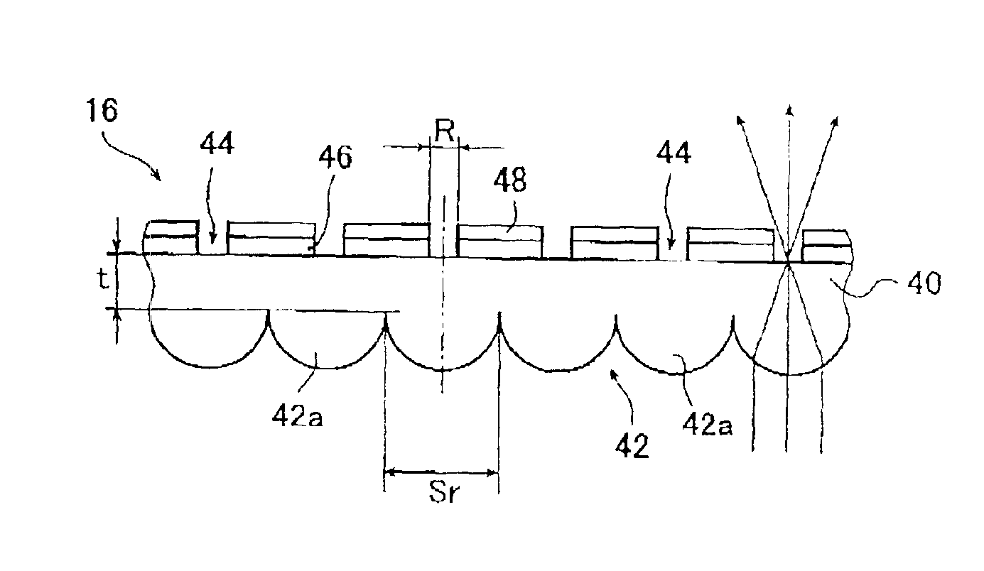
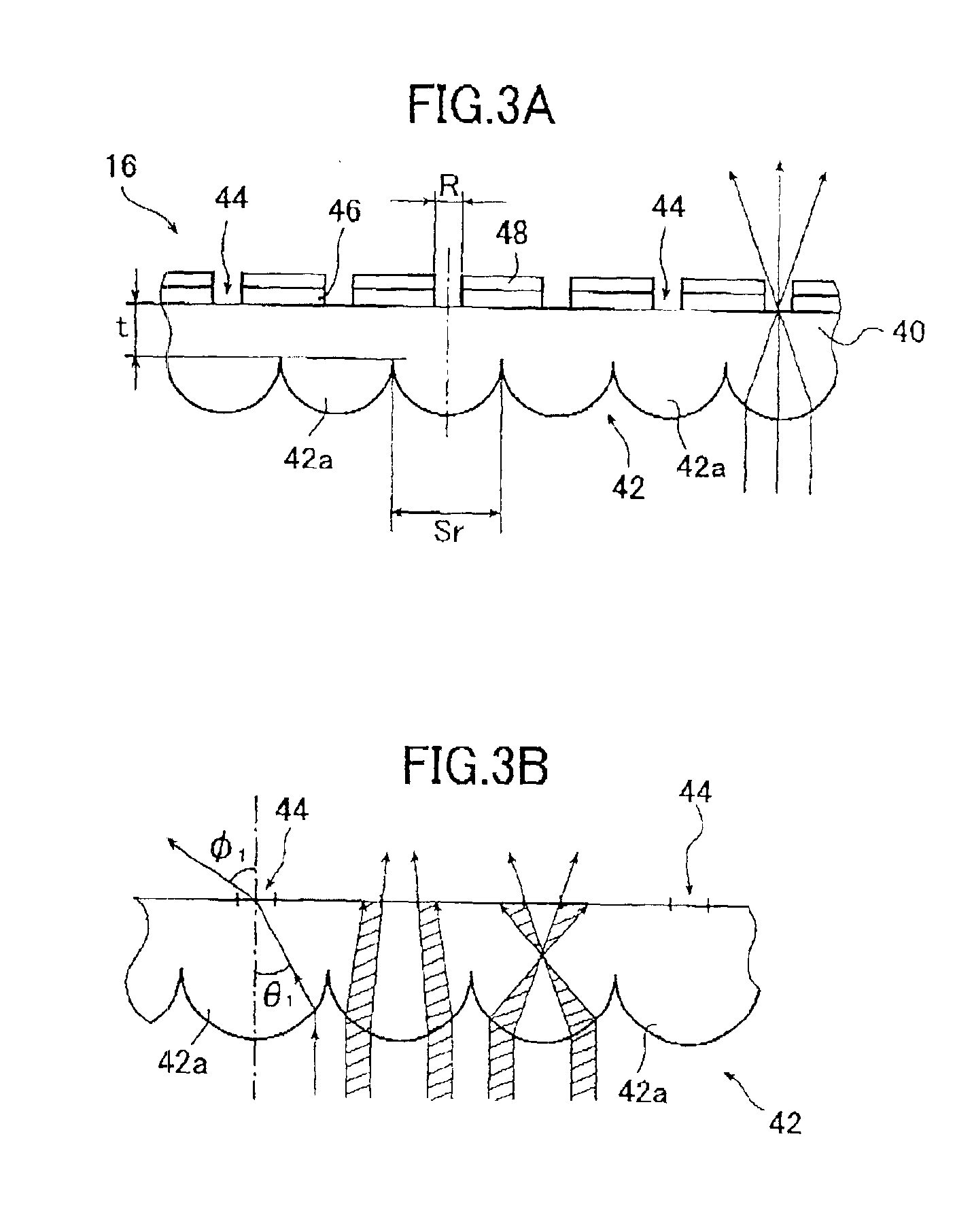
[0119]The light diffusing plate 17 according to the third embodiment of the present invention as shown in FIG. 11A and the light diffusing plate 16 according to the first embodiment of the present invention as shown in FIG. 3A are the same except that the form of the microlens 42a of the microlens array 42 of the former is hemispherical whereas that of the microlens 42b of the microlens array 42 of the latter is semielliptic so that the same numerals as used in the light diffusing plate 16 are used to denote the same components in the light diffusing plate 17 and the detailed description thereof is omitted.
[0120]As shown in FIG. 11A, the light diffusing plate 17 comprise...
PUM
 Abstract
Description
Claims
Application Information