Liquid crystal display element

Inactive Publication Date: 2014-10-23
DAINIPPON INK & CHEM INC
View PDF6 Cites 10 Cited by
  • Summary
  • Abstract
  • Description
  • Claims
  • Application Information

AI Technical Summary

Benefits of technology

[0016]In liquid crystal display devices using homeotropically oriented ferroelectric liquid crystal compositions, when the selective reflection is near infrared or longer, schlieren texture appears to cause a reduction in contrast. In the liquid crystal display device of the present invention, impartment of a pretilt angle by, for example, rubbing orientation treatment of a vertically oriented film surfa

Problems solved by technology

However, the binary display has a problem of a difficulty in provision of gradation display.
As a result, the layer plane is bent from the waist to form a chevron structure, and a zigzag defect is apt to occur, resulting in difficulty in provision of high contrast.
However, the DHFLC described in NPL 2 has a layered structure vertical to the substrate surface, that is, the layer normal direction is approximately parallel to the substrate surface, and the DHFLC therefore has a problem in the viewing angle of the display device.
In this case, however, the chiral dopant concentration is high, resulting in a high melting point.
Consequently, the temperature range of the SmC* phase is narrow to restrict the operating temperature range

Method used


Image

  • Liquid crystal display element
  • Liquid crystal display element
  • Liquid crystal display element

Examples


example 1

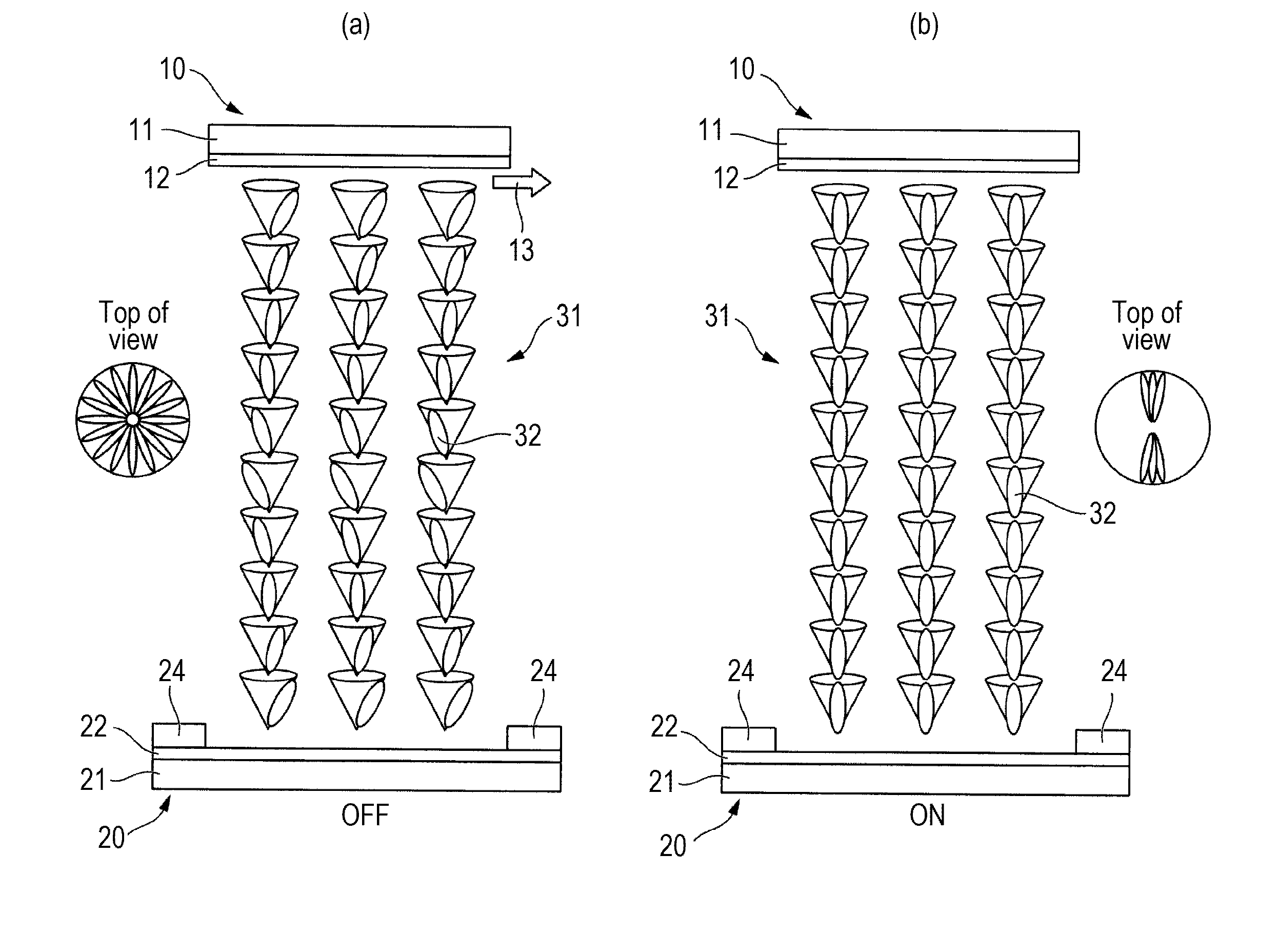
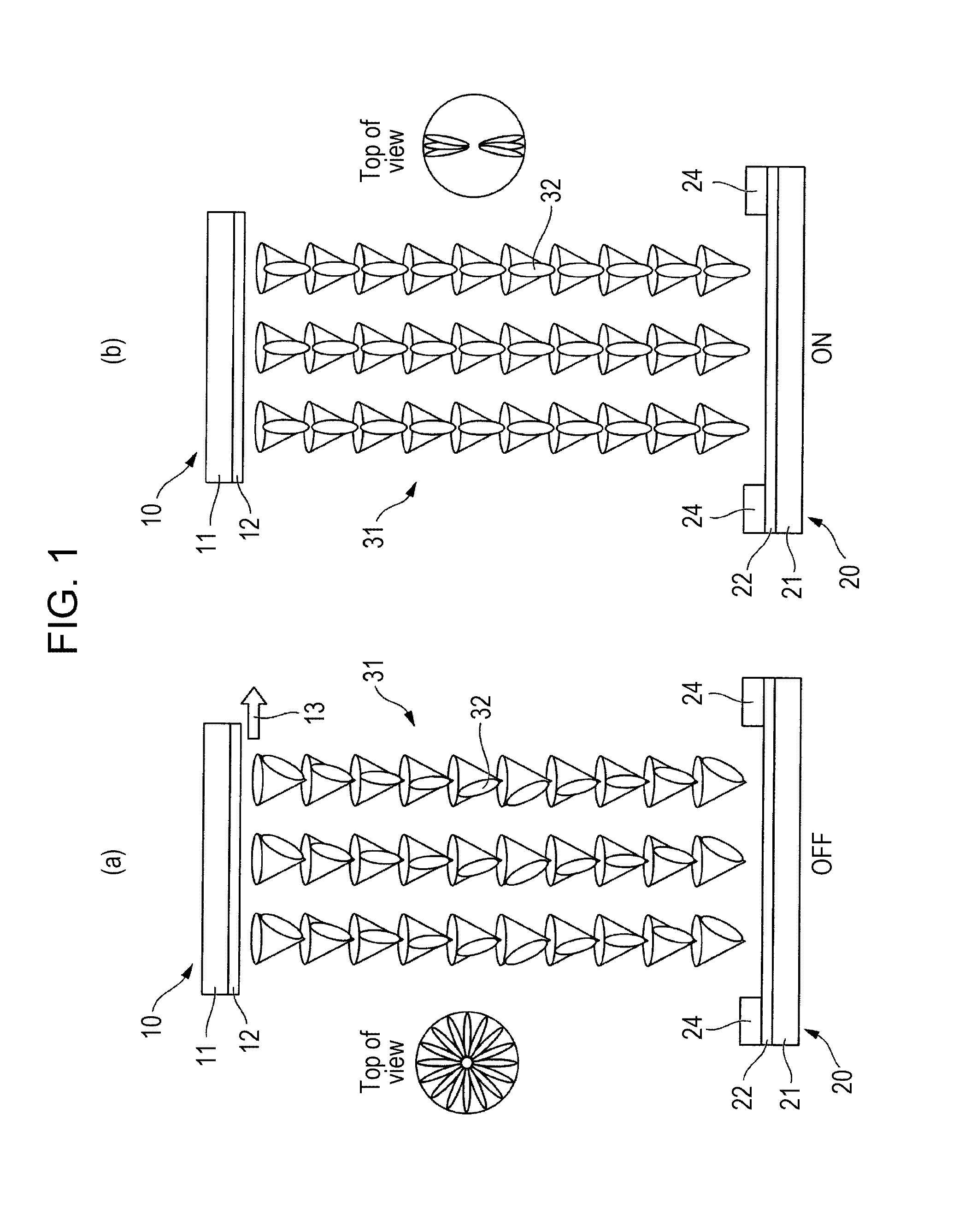
[0266]Two substrates each provided with a vertically oriented film (polyimide vertically oriented film JALS 2096, manufactured by JSR Corporation) were prepared such that the vertically oriented film on the first substrate and the vertically oriented film on the second substrate were antiparallel to each other by rubbing as in parallel orientation, and interdigitated array electrodes (ITO transparent electrodes, distance between the electrodes: 12.5 μm, electrode width: 20 μm) were disposed. The two substrates were faced with a cell thickness (gap) of 4 μm, and a ferroelectric liquid crystal composition LC-1 shown below was injected therein by means of a capillary phenomenon by heating. After the injection, the liquid crystal cell was sealed to produce a liquid crystal display device of Example 1.

[0267]The ferroelectric liquid crystal composition LC-1 was ISO-N*-SmC* phase sequence, in which the phase transition temperature between the ISO and N* phases was 119° C., the phase transi...

example 2

[0274]Two substrates each having a vertically oriented film (polyimide vertically oriented film JALS 2096, manufactured by JSR Corporation) were prepared such that the vertically oriented film on the first substrate and the vertically oriented film on the second substrate were antiparallel to each other by rubbing as in parallel orientation, and interdigitated array electrodes (ITO transparent electrodes, distance between the electrodes: 12.5 μm, electrode width: 20 μm) were disposed. The two substrates were faced with a cell thickness (gap) of 4 μm, and a ferroelectric liquid crystal composition LC-2 shown below was injected therein by means of a capillary phenomenon by heating. After the injection, the liquid crystal cell was sealed to produce a liquid crystal display device of Example 2.

[0275]That is, a liquid crystal display device was produced as in Example 1 except that LC-2 was used, instead of LC-1, as the ferroelectric liquid crystal composition.

[0276]The ferroelectric liqu...

example 3

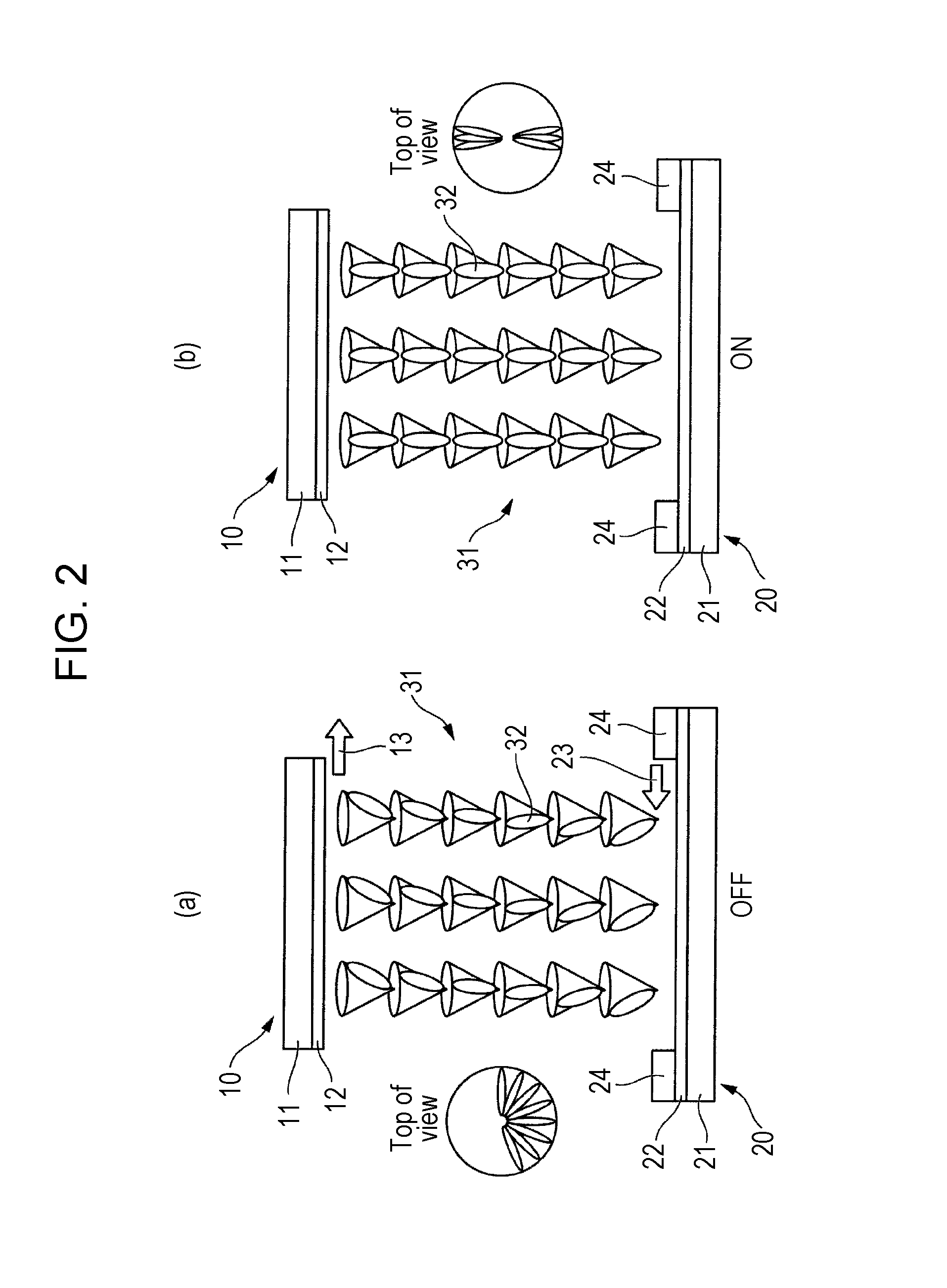
[0280]Two substrates each having a vertically oriented film (polyimide vertically oriented film JALS 2096, manufactured by JSR Corporation) were prepared such that the vertically oriented film on the first substrate and the vertically oriented film on the second substrate were antiparallel to each other by rubbing as in parallel orientation, and interdigitated array electrodes (ITO transparent electrodes, distance between the electrodes: 12.5 μm, electrode width: 20 μm) were disposed. The two substrates were faced with a cell thickness (gap) of 14 μm, and a ferroelectric liquid crystal composition LC-4 shown below was injected therein by means of a capillary phenomenon by heating. After the injection, the liquid crystal cell was sealed to produce a liquid crystal display device of Example 3.

[0281]An orientation-free smectic A phase was obtained from a nematic phase by slow cooling at a rate of 2° C. / min from a temperature higher by 3° C. than a phase transition temperature (109° C.)...


PUM


Abstract

A ferroelectric liquid crystal composition having a chiral smectic C-phase is disposed as a liquid crystal composition layer between a first substrate and a second substrate arranged between two polarizing plates of which the planes of polarization are orthogonal to each other. The substrates are provided with vertically oriented films, respectively, and at least one of them is provided with orientation treatment that can form a pretilt angle in a certain direction. The C-director of the liquid crystal molecule is oriented in the certain direction at a portion being in contact with the substrate provided with the orientation treatment and is twisted by at least 180° between the first substrate and the second substrate. At least one of the substrates is provided with a pair of electrode structures generating electric fields approximately parallel to each other.

Description

TECHNICAL FIELD[0001]The present invention relates to a liquid crystal display device including a ferroelectric liquid crystal composition.BACKGROUND ART[0002]Ferroelectric liquid crystal (FLC) shows ferroelectricity through spontaneous polarization. It is known that liquid crystal having a permanent dipole moment in a direction vertical to the molecular long axis direction forms a layer structure of a smectic phase and that the permanent dipole moment is not cancelled as an average whole in changing to a chiral smectic C (hereinafter, abbreviated to SmC*) phase by tilting of the molecular long axis in this layer and thereby spontaneous polarization is caused to show ferroelectricity. Application of a voltage to the ferroelectric liquid crystal allows the permanent dipole moment to be directed to the electric field and simultaneously allows the whole molecule to be aligned. The ferroelectric liquid crystal widely used in displays is of SmC* phase. Ferroelectric liquid crystal impart...

Claims


Application Information

Patent Timeline
IPC IPC(8): G02F1/141
CPCG02F1/1418G02F1/141G02F1/1416G02F2202/40G02F1/133761G02F1/1414
Inventor FUJISAWA, TORUHATSUSAKA, KAZUAKIMARUYAMA, KAZUNORINISHIYAMA, ISA
Owner DAINIPPON INK & CHEM INC
Why Eureka
Try Eureka