Method and apparatus for filter condition inspection

a filter and condition inspection technology, applied in the direction of radiation pyrometry, exhaust treatment, instruments, etc., can solve the problems of affecting the integrity of the filter, affecting the operation of the filter, so as to reduce the contrast, reduce the length of the blockage, and reduce the effect of blocking

Active Publication Date: 2015-04-21
CERAMEX
View PDF12 Cites 1 Cited by
  • Summary
  • Abstract
  • Description
  • Claims
  • Application Information

AI Technical Summary

Benefits of technology

[0013]The present invention offers the possibility of gaining a measurement of the depth of blockage. This seems most achievable when the blockages are in contact with the end plugs at the hot face of the filter and the blockage length is relatively short. It would appear that when these conditions are met, heat is able to conduct through the ash in sufficient amount and time to provide a rapid detectable change in contrast against the background. As the surfaces within the filter become warmer they too radiate heat. This re-radiation of heat appears to outpace conduction once the hot face temperature builds and this steadily reduces contrast across the whole filter. Heavily blocked cells remain in high contrast for much longer but detecting the amount of blockage becomes more difficult.

Problems solved by technology

The above-described wall-flow filters can become contaminated with soot and ash in the course of their operation on heavy-duty diesel-powered vehicles.
However, under adverse conditions, for example where the vehicle undertakes a large amount of city driving where high temperatures of exhaust gases are not reached, or after prolonged use, the filter can become blocked.
Once the filter is blocked, even locally, it can be damaged by the heat generated from the exothermic reaction of carbon with oxygen.
When severe reactions occur the integrity of the filter is damaged and its effectiveness reduced.
However, we have found that the method does not work well with other filter materials such as silicon carbide, where even clean filters transmit very little light.
We have also found that the prior art method is ineffective for filters in which the ceramic material is provided with a catalytic coating, typically by dipping it into a slurry of insoluble particles such as alumina interspersed with metal and then drying it off.
The way in which filters operate in service generally results in ash consolidating at the bottom of the cell against the end plugs on the outlet face.
It follows that the most difficult area of a cell to clean is that portion just behind the end plug.
Therefore in practice when complete cleaning is not achieved, blockage is generally found in at the bottom of the cell against the end plug.
However, knowing the number or percentage of cells with blockage does not provide a complete picture of filter condition.

Method used


Image

  • Method and apparatus for filter condition inspection
  • Method and apparatus for filter condition inspection
  • Method and apparatus for filter condition inspection

Examples


Embodiment Construction

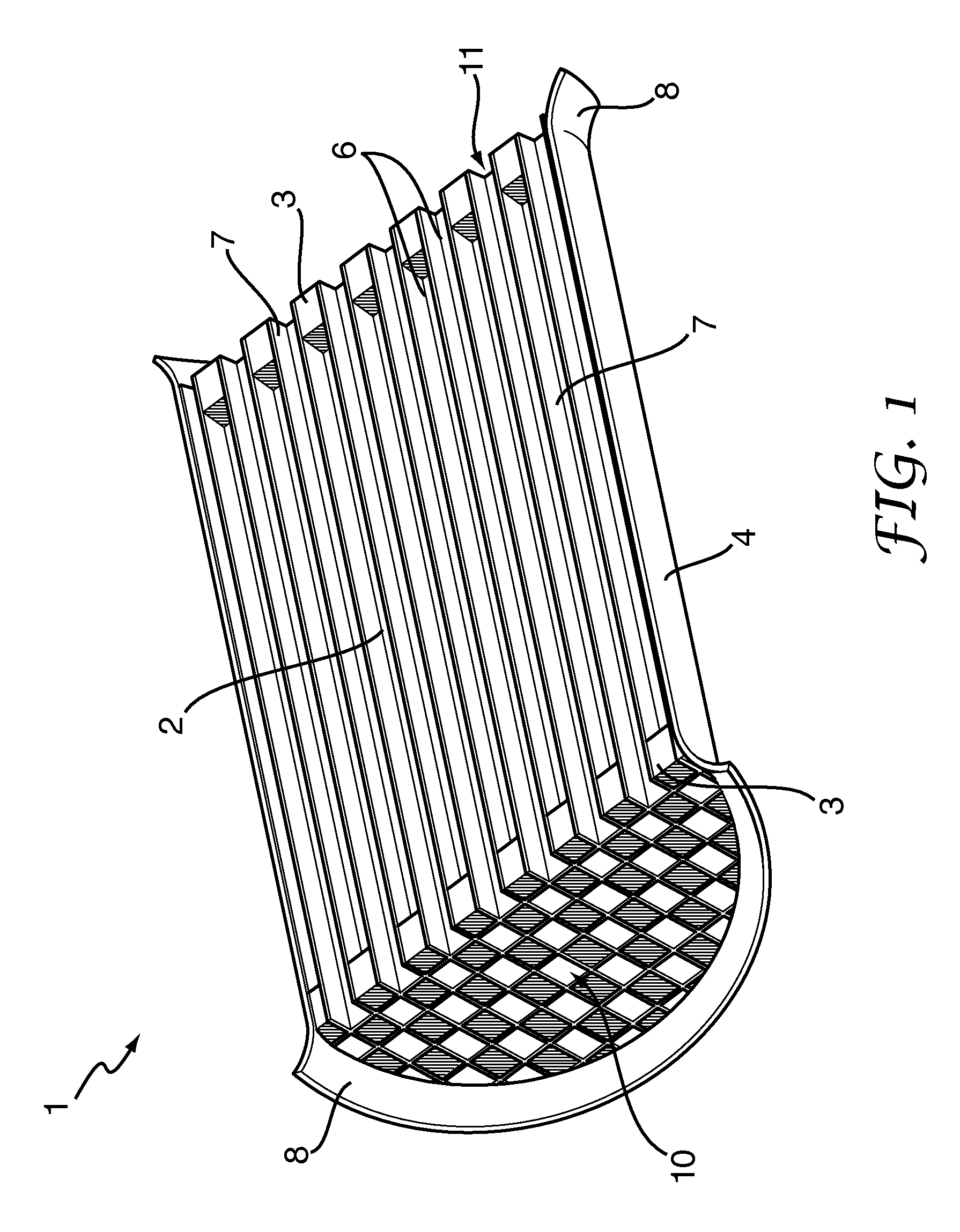
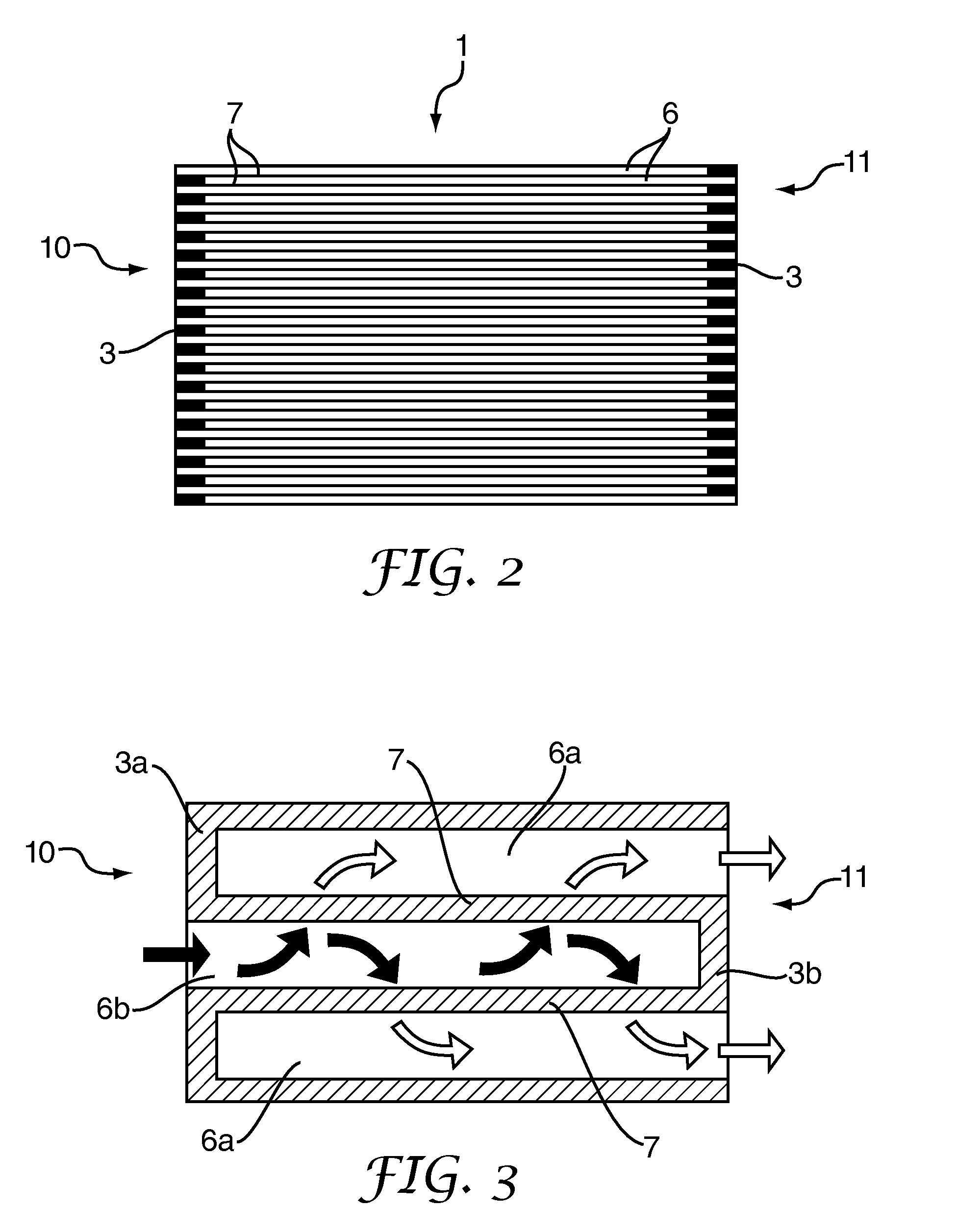
[0050]FIGS. 1 and 2 show a schematic diagram of a wall-flow filter 1 comprising a cylindrical ceramic monolith core 2 contained within a cylindrical metal surround or sleeve 4. The overall diameter of a filter 1 for a vehicle exhaust system is generally between 100 and 400 mm. The ceramic filter cores 2 have a number of elongate channels 6 running along their length. These channels 6 generally have an approximately square cross-section and are about 0.6-2 mm in width. In FIG. 1 the relative size of the channels 6 compared to the dimensions of the filter 1 has been increased for clarity. Between the channels 6 the walls 7 of the filter core 2 are formed from a porous ceramic. The ceramic may be, for example, cordierite (magnesium iron aluminium cyclosilicate), silicon carbide, or aluminium titanate. Typical porosities are between 40 and 50% with a mean pore size between 10 and 20 μm, or smaller for Euro 6 filters. Neighbouring channels 6 in the filter 1 are plugged at alternate ends ...


PUM

PropertyMeasurementUnit
peak wavelengthaaaaaaaaaa
temperatureaaaaaaaaaa

Abstract

A method of inspecting a ceramic wall-flow filter (1) for a vehicle exhaust system includes the steps of: a) providing a source (9) of heat energy suitable for heating material within the filter (1); b) applying heat energy from the source (9) to a first end (10) of the filter (1) to heat material within the filter; c) detecting infrared radiation (18) which has been emitted by heated material in the filter using a radiation detector (19) at the second end (11) of the filter (1) to form an image (24) of a pattern of emitted radiation, the pattern of emitted radiation providing an indication of the condition of the filter (1). Another aspect of the invention provides apparatus for use in the method.

Description

[0001]The invention relates to a method and apparatus for inspecting the condition of a ceramic wall-flow filter for a vehicle exhaust system. The invention is particularly applicable to the inspection of filters such as continuously regenerating diesel particulate filters (CR-DPFs).[0002]Modern diesel powered vehicle exhaust systems are often provided with filters for removing particulate matter from the vehicle's exhaust stream. These are typically wall-flow filters which are cylindrical ceramic monoliths having elongate channels running along their length, parallel to the axis of the cylinder. The channels are alternately plugged at their ends such that gas entering a channel at one end cannot exit the same channel at its other end. To exit, the gas must pass from one channel to the next through the porous walls of the filter. In so doing, the soot and ash within the gas is trapped on the walls of the filter.[0003]A preferred filter for a modern diesel exhaust system is a continu...

Claims


Application Information

Patent Timeline
Patent Type & Authority Patents(United States)
IPC IPC(8): G01J5/02F01N3/022F01N3/027F01N3/028F01N3/035F01N9/00F01N11/00F01N13/00G01N21/94G01N22/02G01N25/72
CPCG01N21/94F01N3/0222F01N3/027F01N3/028F01N3/035F01N9/002F01N13/008G01N25/72F01N11/002F01N2330/06F01N2390/00F01N2550/04G01N22/02Y02T10/47Y02T10/40
Inventor FORSTER, PETER IVAN
Owner CERAMEX
Why Eureka
Try Eureka