Eureka AIR delivers breakthrough ideas for toughest innovation challenges, trusted by R&D personnel around the world.

Mask blank for EUV exposure and mask for EUV exposure

Active Publication Date: 2009-03-19
NEC CORP +1
View PDF5 Cites 1 Cited by
  • Summary
  • Abstract
  • Description
  • Claims
  • Application Information

AI Technical Summary

Benefits of technology

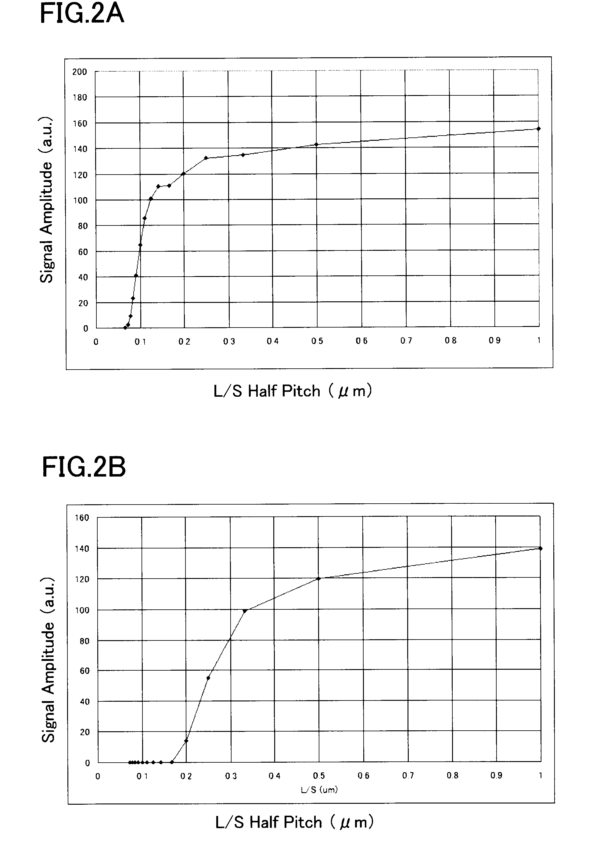
[0007]Even if an antireflection layer with respect to ultraviolet is provided above the absorbent layer, the contrast in the ultraviolet inspection light remarkably decreases when the line and space of the pattern (line widths and line spacing) get narrow as the same order as the wavelength order of the inspection light. The reason for this is as follows. A small amount of inspection light is always reflected on the surface of the pattern (i.e. the surface of the absorbent layer) regardless of the pattern size. In contrast to this, if the space part of the pattern (i.e. the space of the absorbent layer) approaches the wavelength order, the inspection light is hardly reflected at the space part of the pattern in the form of a concave, thus decreasing the difference between the reflectance values of respective positions with and without the absorbent layer.
[0008]The present invention has been made in consideration of the above matter. An object thereof is to provide a mask for EUV exposure and a mask blank for EUV exposure for manufacturing the same, so as to improve the contrast with respect to ultraviolet inspection light and to improve the inspection performance for the mask.

Problems solved by technology

Thus, an optical lithographic system cannot be formed of lens and the like previously used, and required to be formed entirely of mirror optical systems.
However, in the mask having optimum reflection characteristics with respect only to EUV light, there is a high chance that no sufficient contrast exists in the ultraviolet inspection light that has different wavelengths.

Method used


Image

  • Mask blank for EUV exposure and mask for EUV exposure
  • Mask blank for EUV exposure and mask for EUV exposure
  • Mask blank for EUV exposure and mask for EUV exposure

Examples


first embodiment

[0017]A mask blank (or mask blanks) for EUV exposure of a first embodiment of the present invention includes a substrate, a reflecting layer which is provided on this substrate and reflects EUV light, and an absorbent layer which is provided on the reflecting layer and absorbs EUV light. At the absorbent layer, the reflectance of light at a wavelength between 150 nm and 300 nm is greater than that at the reflecting layer.

[0018]A mask for EUV exposure of the first embodiment of the present invention includes a substrate, a reflecting layer which is provided on this substrate and reflects EUV light, and an absorbent layer which is provided on the reflecting layer and has a predetermined pattern for absorbing EUV light. At the absorbent layer, the reflectance of light at a wavelength between 150 nm and 300 nm is greater than that at the reflecting layer. That is, for example, the mask is manufactured by patterning the absorbent layer of the above-described mask blank for EUV exposure i...

second embodiment

[0042]A mask blank for EUV exposure (or mask blanks) of a second embodiment of the present invention is the same as that of the first embodiment except that the absorbent layer is a single layer of Cr. Thus, the same descriptions as those of the first embodiment will not be made again in this embodiment.

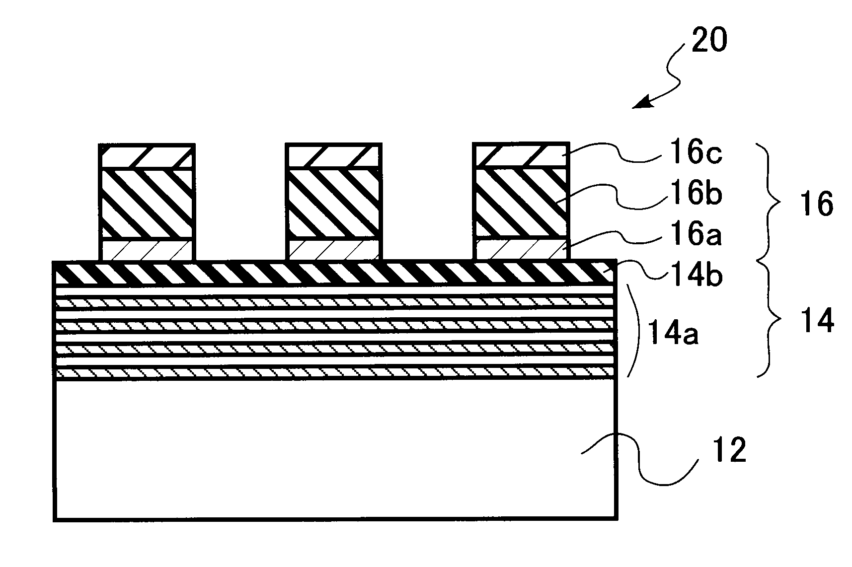
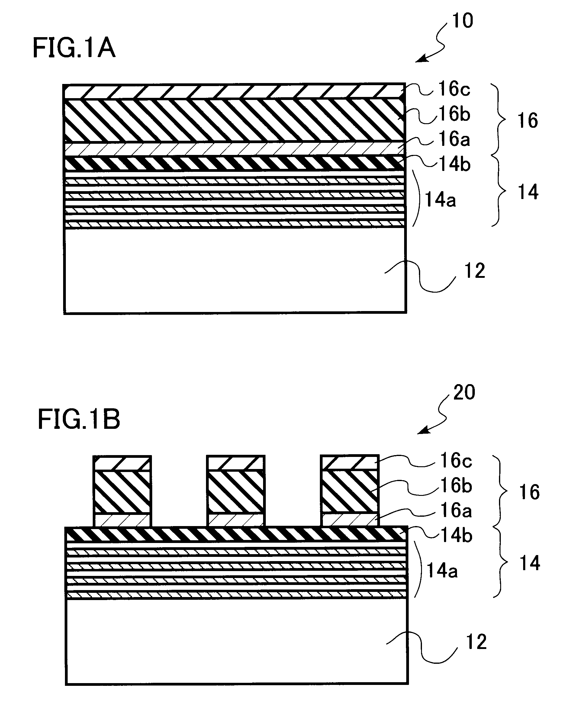
[0043]FIG. 4A and FIG. 4B are cross sectional views of a mask blank and mask of this embodiment. FIG. 4A shows the mask blank, while FIG. 4B shows the mask which is manufactured by processing this mask blank.

[0044]As described in FIG. 4A and FIG. 4B, each of the mask blank 10 and mask 20 of this embodiment includes the substrate 12, the reflecting layer 14 which is provided on this substrate 12 and reflects EUV light, and the absorbent layer 16 which is provided on the reflecting layer 14 and absorbs EUV light. In this case, the reflectance of the reflecting layer 14 with respect to EUV light is greater than that of the absorbent layer 16. The absorptivity of the absorbent layer 16 w...


PUM

PropertyMeasurementUnit
Lengthaaaaaaaaaa
Thicknessaaaaaaaaaa
Wavelengthaaaaaaaaaa

Abstract

Provided are a mask for EUV exposure and a mask blank for EUV exposure for manufacturing the same, so as to improve the contrast of ultraviolet inspection light and improve the inspection performance for the mask. This mask blank for EUV exposure includes a substrate, a reflecting layer which is provided on the substrate and reflects EUV light, and an absorbent layer which is provided on the reflecting layer and absorbs EUV light. Reflectance of light at a wavelength between 150 nm and 300 nm is greater at the absorbent layer than that of the reflecting layer. The mask for EUV exposure can be manufactured by processing this mask blank for EUV exposure.

Description

CROSS-REFERENCE TO RELATED APPLICATION[0001]This application is based upon and claims the benefit of priority from Japanese Patent Applications No. 2007-240466, filed on Sep. 18, 2007, the entire contents of which are incorporated herein by reference.FIELD OF THE INVENTION[0002]The present invention relates to a mask for EUV exposure for use in manufacturing semiconductor devices, etc. and also a mask blank for EUV exposure for manufacturing the same.BACKGROUND OF THE INVENTION[0003]As the integration of ICs increases, exposure wavelengths become shorter in lithography. This is because the resolution in the optical exposure generally improves as the exposure wavelengths become short. Recently, the exposure wavelengths have been shortened from a KrF laser of 248 nm to an ArF laser of 193 nm. As the exposure wavelengths in the next-generation lithography, a remarkably shortened wavelength between 12 nm and 15 nm using extreme ultraviolet (hereinafter referred to as EUV) light is promi...

Claims


Application Information

Patent Timeline
IPC IPC(8): G03F1/00G03F1/22G03F1/24H01L21/027
CPCB82Y10/00G03F1/24B82Y40/00Y10T428/31616
Inventor HIRONO, MASATOSHI
Owner NEC CORP
Why Eureka
Eureka Blog
Learn More