Color splitting/combining optical system and image projecting apparatus

Inactive Publication Date: 2006-11-21
CANON KK
View PDF31 Cites 9 Cited by
  • Summary
  • Abstract
  • Description
  • Claims
  • Application Information

AI Technical Summary

Benefits of technology

[0022]It is therefore an object of the invention to provide a color splitting/combining optical system, in which color-selective wave plates and polarization splittin

Problems solved by technology

However, since the reflectivity of the dichroic mirror is not 100% and the wavelength characteristics thereof shift in accordance with the incident angle, it is impossible that the light amoun

Method used


Image

  • Color splitting/combining optical system and image projecting apparatus
  • Color splitting/combining optical system and image projecting apparatus
  • Color splitting/combining optical system and image projecting apparatus

Examples


Example

(Embodiment 1)

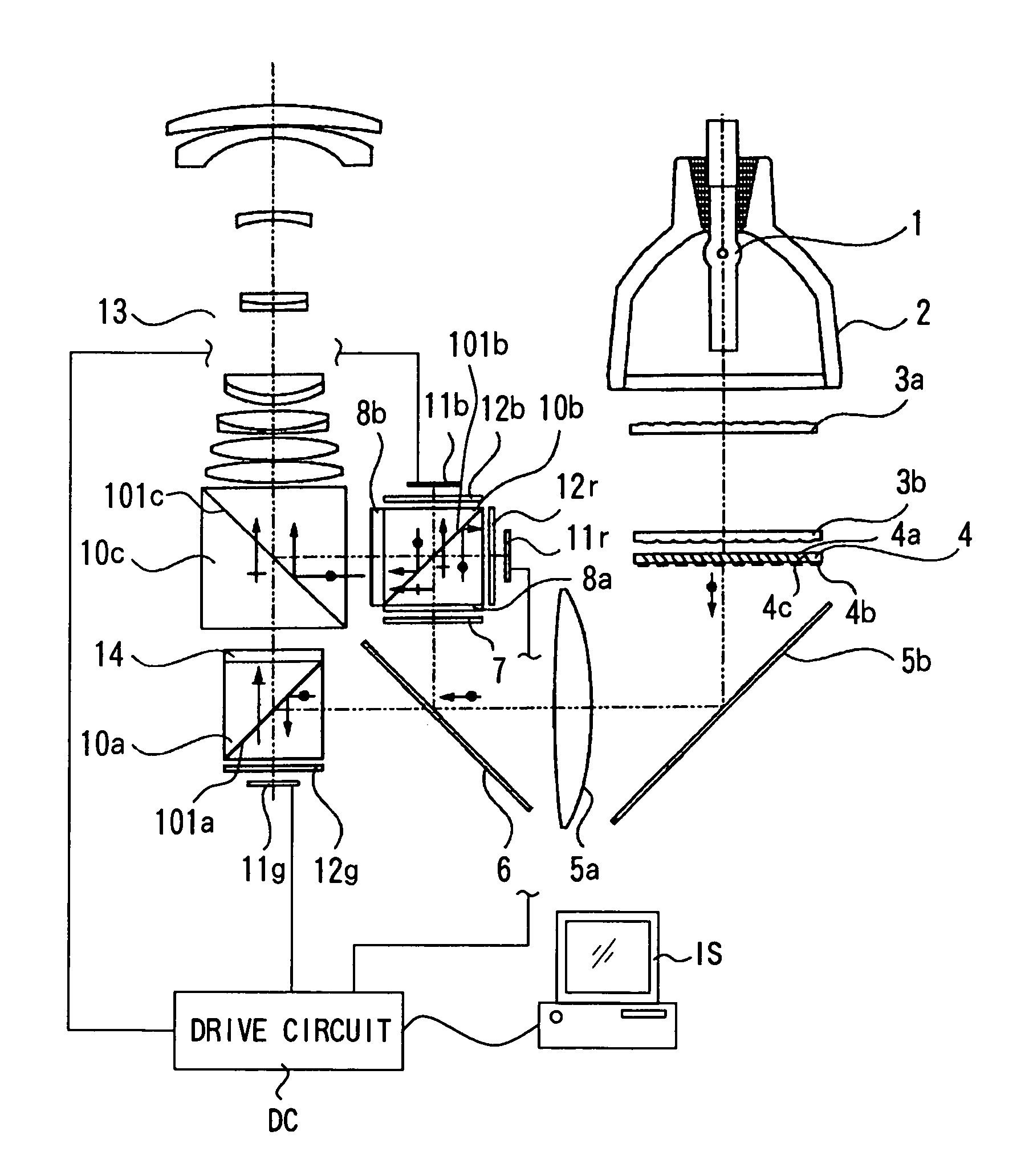
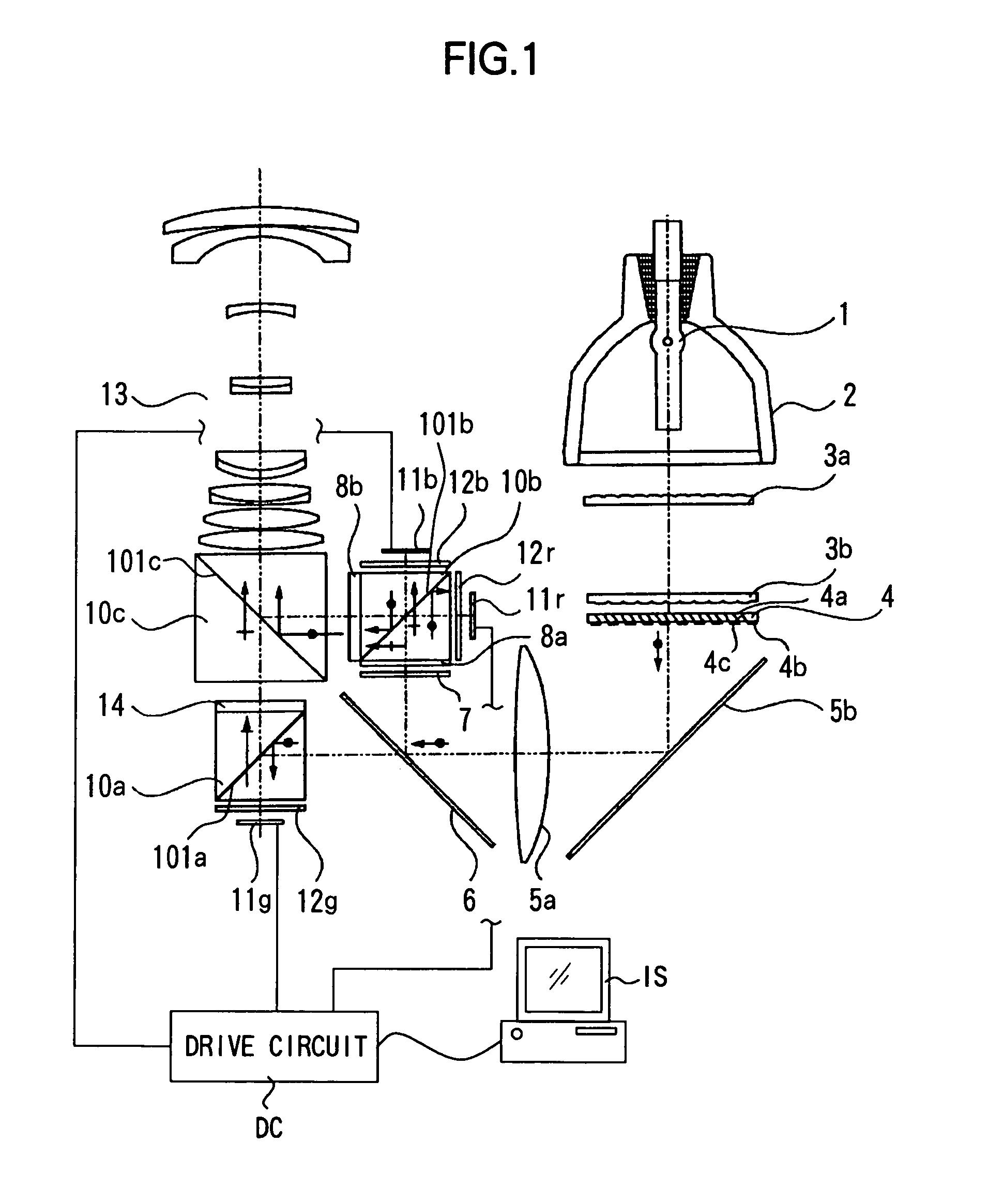
[0072]FIG. 1 is a view representing Embodiment 1 according to the present invention. In the drawing, Reference Numeral 1 denotes a light source which emits white-color light with a continuous spectrum. Reference Numeral 2 denotes a reflector which condenses light in a predetermined direction. Reference Numeral 3a denotes a first fly-eye lens having rectangular lenses disposed in a matrix state, and 3b denotes a second fly-eye lens constituted by lens arrays corresponding to respective lenses of the first fly-eye lens.

[0073]Reference Numeral 4 denotes a polarization converting element which makes non-polarized light into predetermined polarized light. Reference Numeral 5a denotes a condenser lens and 5b denotes a mirror. Reference Numeral 6 denotes a dichroic mirror which is a first optical member, which reflects light components of wavelength regions of blue (B) and red (R) and transmits a light component of a wavelength region of green (G).

[0074]Reference Numeral 7 de...

Example

(Embodiment 2)

[0093]FIG. 4 is a view representing Embodiment 2 according to the present invention, wherein parts which are identical to those in Embodiment 1 are given the same Reference Numerals. A point in which Embodiment 2 differs from Embodiment 1 resides in that the arrangement of the reflection type liquid crystal display element for R and the reflection type liquid crystal display element for B is reversed. Therefore, in Embodiment 2, the first color-selective wave plate 28a which converts the polarization direction of the light component of R by 90 degrees but does not convert the polarization direction of the light component of B, and the second color-selective wave plate 28b which converts the polarization direction of the light component of B by 90 degrees but does not convert the polarization direction of the light component of R are provided.

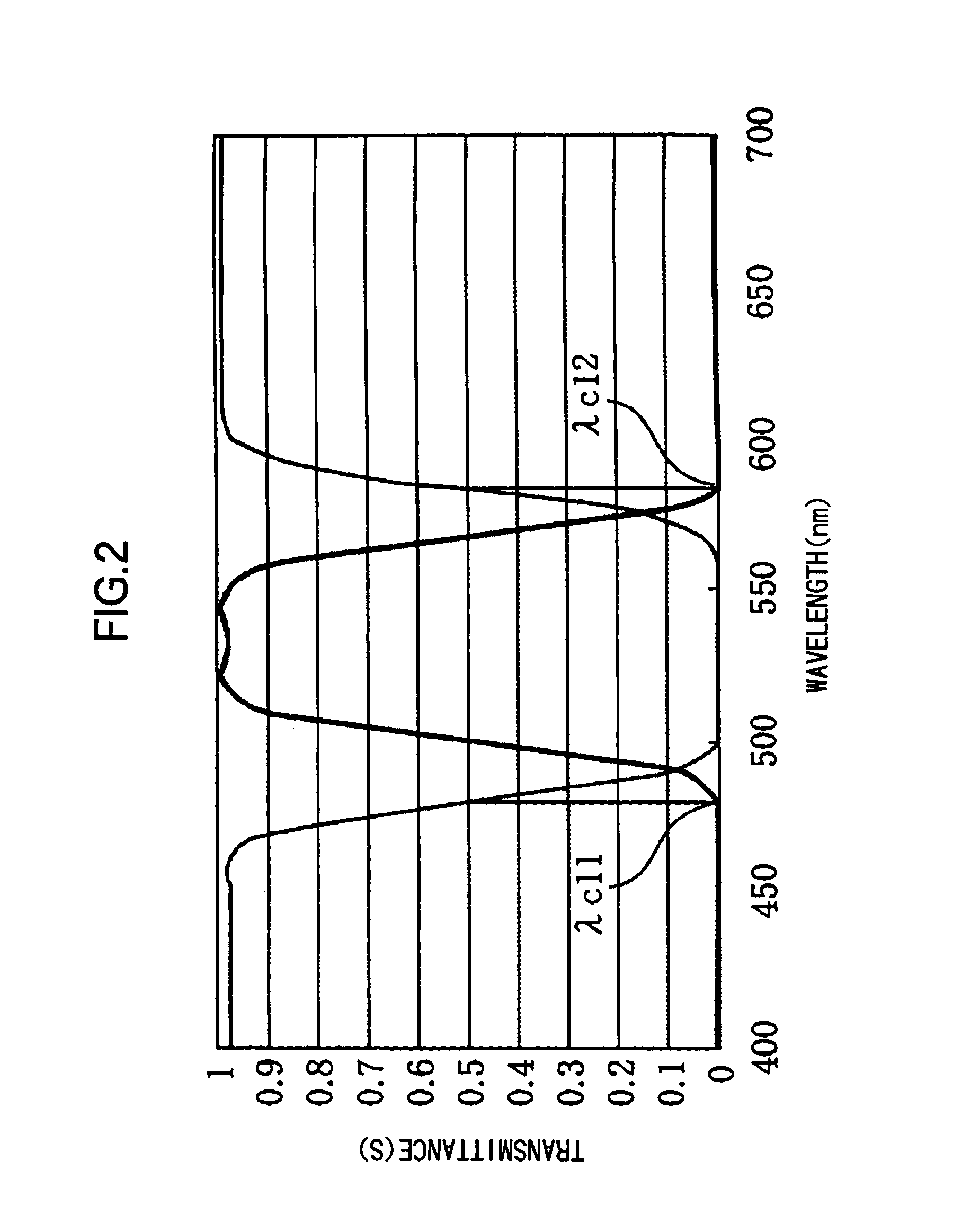
[0094]FIG. 5 shows the characteristics of the first color-selective wave plate according to the present embodiment with thick lin...

Example

(Embodiment 3)

[0102]FIG. 6 is a view representing Embodiment 3 according to the present invention, wherein parts which are identical to those of Embodiment 1 are given the same Reference Numerals. A point in which Embodiment 3 differs from Embodiment 1 resides in that Embodiment 3 is provided with a polarization converting element 34 by which non-polarized light is aligned to be P-polarized light. Therefore, a first color-selective wave plate 38a which converts the polarization direction of the light component of R by 90 degrees but does not convert the polarization direction of the light component of B, and a second color-selective wave plate 38b which rotates the polarization direction of the light component of R by 90 degrees but does not convert the polarization direction of the light component of B are provided therein, and the ½ wave plate 31 which converts the polarization direction of light G by 90 degrees is provided at the incidence side of the first polarization beam spli...


PUM


Abstract

A color splitting/combining optical system includes a first optical member for color splitting and a second optical member which has a polarization splitting surface for color splitting/combining, a third optical member for color combining a first color-selective wave plates and a second color-selective wave plate. The first and second color-selective wave plates convert the polarization direction of light in a first and second wavelength regions respectively by 90 degrees. The optical system satisfies λ1≠λ2, where λ1 and λ2 represent wavelengths in which the ratio of the light component having the polarization direction converted by 90 degrees by the first and second color-selective wave plates respectively become substantially 50%.

Description

BACKGROUND OF THE INVENTION[0001]1. Field of the Invention[0002]The present invention relates to a color splitting / combining optical system used for an image projection apparatus (projector) for projecting light from image-forming elements which form an original picture.[0003]2. Description of Related Art[0004]An image projection apparatus in which reflection type liquid crystal display elements and a polarization beam splitter are combined with each other is disclosed by Japanese Patent Application Laid-open No. 2001-154268. The corresponding image projection apparatus is an image projection apparatus having a white-color light source 1001, reflection type liquid crystal display elements 1002R, 1002G and 1002B, and a projection optical system 1003 as shown in FIG. 33. In the corresponding image projection apparatus, a dichroic mirror 1004 is provided between the white-color light source 1001 and the reflection type liquid crystal display elements 1002R, 1002G and 1002B. Further, th...

Claims


Application Information

Patent Timeline
IPC IPC(8): G03B21/14G02F1/13363G02B27/28G02B27/18G03B21/00H04N9/31
CPCH04N9/3105H04N9/3167H04N9/3197
Inventor OKUYAMA, ATSUSHIABE, MASAYUKI
Owner CANON KK
Why Eureka
Try Eureka