
Mobile radio communication system, communication apparatus applied in mobile radio communication system, and mobile radio communication method

a mobile radio communication system and communication apparatus technology, applied in multiplex communication, power management, wireless commuication services, etc., can solve the problems of increasing the size of the constitution of the receiver, complicated constitution of the base station and the network, and large so as to reduce the compression ratio and suppress the number of spreading codes of a shorter code length

Inactive Publication Date: 2005-05-24
MITSUBISHI ELECTRIC CORP
View PDF15 Cites 23 Cited by
  • Summary
  • Abstract
  • Description
  • Claims
  • Application Information

AI Technical Summary

Benefits of technology

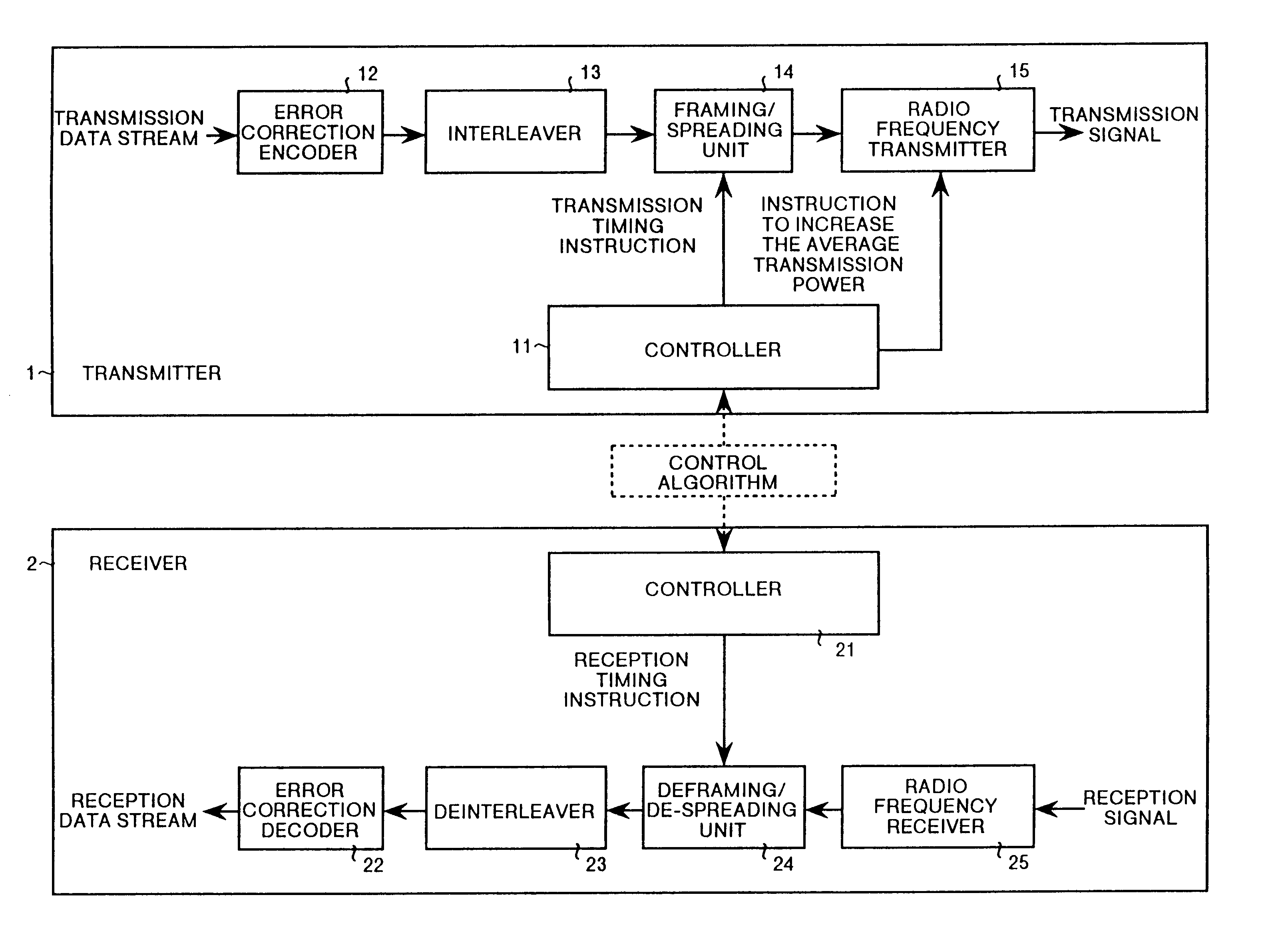
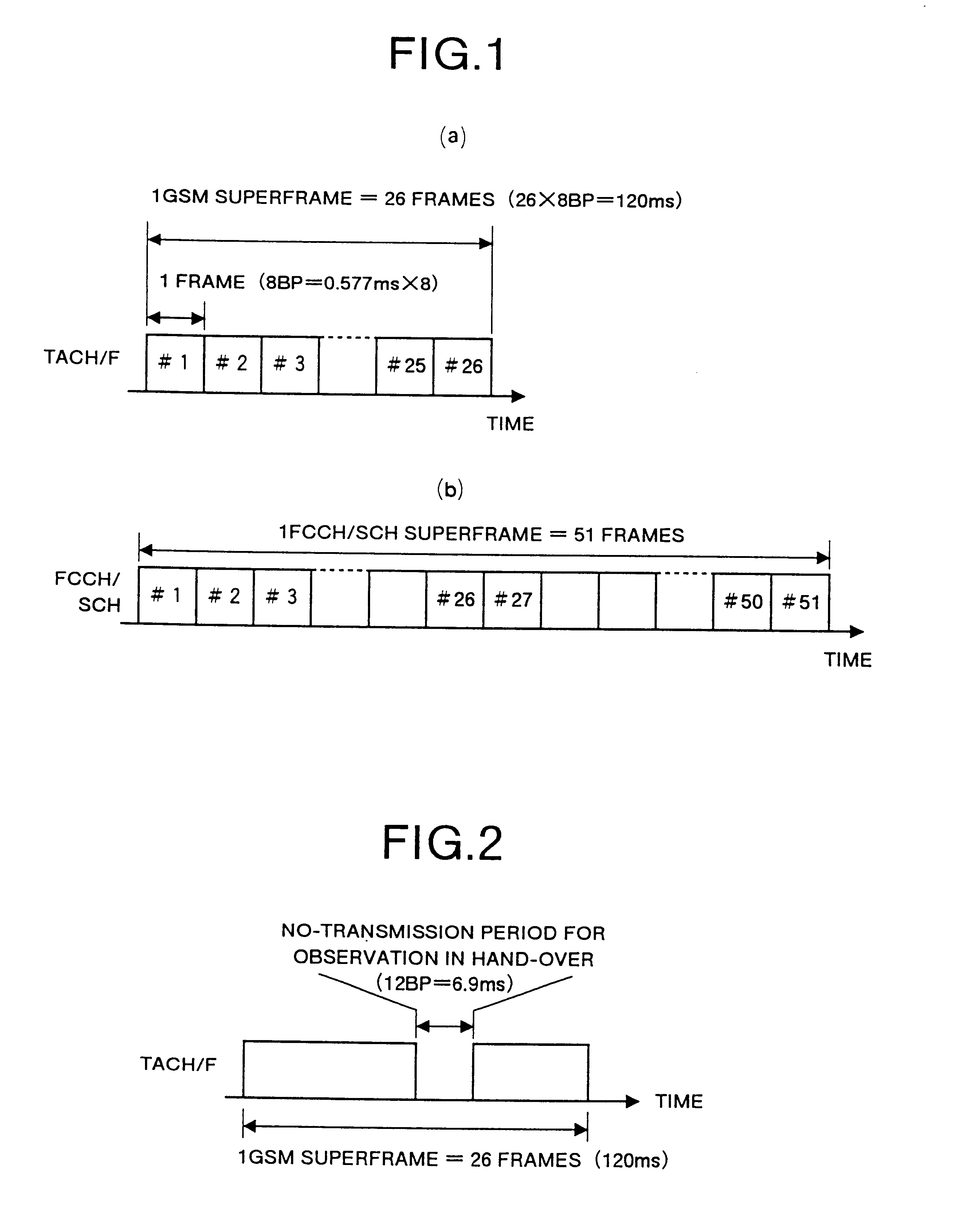
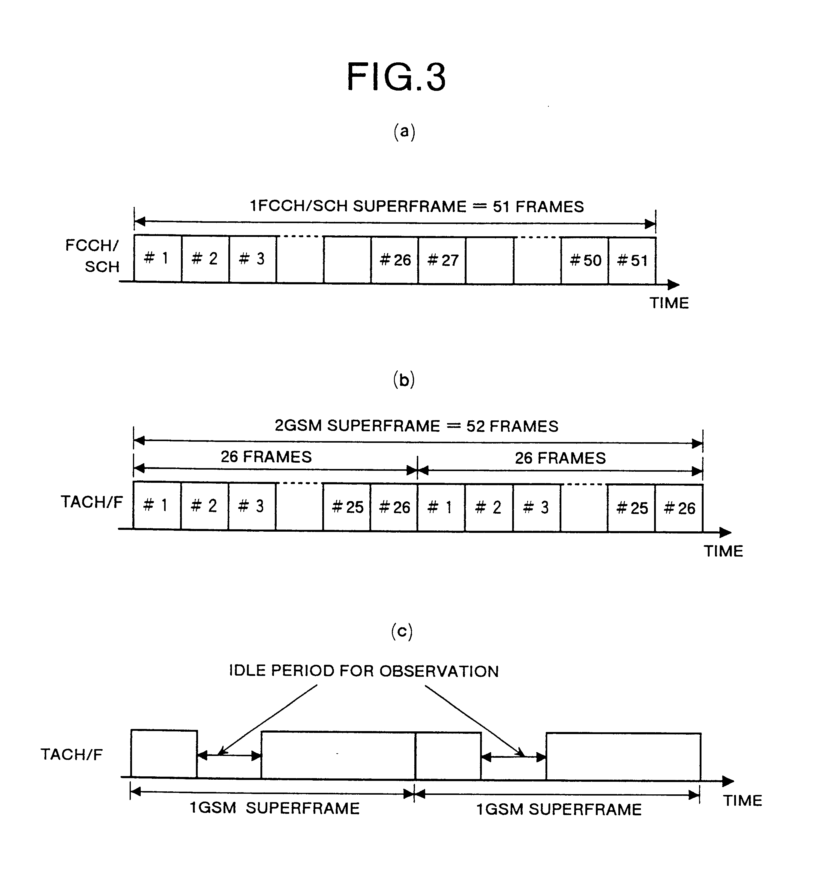
The invention is a mobile radio communication system that includes two communication systems that use different methods for transmitting frames. The first system uses a first superframe made up of multiple frames to transmit data, while the second system uses a second superframe of equal transmission period to observe the frequency component of the control data transmission channel. The system also includes an idle period that allows for the observation of the frequency component of the control data transmission channel in the second system without interfering with frame transmission in the first system. This allows for secure observation of the frequency component of the second system without affecting the interleaving performance of the first system. The invention also takes into account the differences in transmission periods between the two systems to optimize the use of idle periods and improve interleaving performance.

Problems solved by technology

However, this increases the size of the constitution of the receiver, or makes the constitution complicated.
However, it is necessary to synchronize the mobile device and the base station, whereby the constitution of the base station and the network becomes complicated and large in order to be capable of tracking each dedicated mobile device.
However, in the existing technology, due to restrictions in the error correction code and spreading factor for frame transmission, it is difficult to insert all observation period in one frame, and there are many other problems.

Method used


Image

  • Mobile radio communication system, communication apparatus applied in mobile radio communication system, and mobile radio communication method
  • Mobile radio communication system, communication apparatus applied in mobile radio communication system, and mobile radio communication method
  • Mobile radio communication system, communication apparatus applied in mobile radio communication system, and mobile radio communication method

Examples


first embodiment

[0101]In the first embodiment, the frequency is observed and detected twice in every one UMTS superframe. Hence, in two UMTS superframes, the frequency is observed and detected four times.

[0102]The observation and detection method is explained by referring to FIG. 7. FIG. 7 is a diagram for explaining the frame transmission of downlink in the first embodiment of the invention. In FIG. 7, the axis of ordinates denotes the transmission rate or transmission power, and the axis of abscissas represents the time. There is a difference of one frame between one FCCH / SCH superframe and two UMTS superframes in the common control channel. In the dedicated traffic channel TACH / F, the position of observation period assigned in one GSM superframe is fixed. Similarly, in the UMTS also the positions of two observation periods assigned in one UMTS superframe in the downlink traffic channel are fixed. Therefore, frequency is observed and detected in specified frames (two positions) of every UMTS supe...

second embodiment

[0133]The observation and detection method of the second embodiment is explained below. FIG. 11 is a diagram for explaining the frame transmission of downlink according to the embodiment of the invention. In FIG. 11, the axis of ordinates denotes the transmission rate or transmission power, and the axis of abscissas represents the time. In comparison between one FCCH / SCH superframe and two UMTS superframes in the common control channel, there is a difference of one frame. In the dedicated traffic channel TACH / F, the position of observation period assigned in one GSM superframe is fixed. Similarly in the UMTS, the positions of four observation periods assigned in one UMTS superframe in the downlink traffic channel are fixed. Therefore, the frequency is observed and detected in specified frames (four positions) of every UMTS superframe. Thus, since there is a difference of one frame between one FCCH / SCH superframe and two UMTS superframes, one frame is shifted each in each observation...


PUM


Abstract

In the mobile radio communication system where the UMTS and an another system coexist an idle slot for observing the frequency component of another system is inserted in one superframe of UMTS. The duration of this idle slot is at most half of the duration of one frame that form the superframe and it is inserted at an interval of a specified number of frames. Therefore, the frequency component of the another system can be observed securely from the UMTS. Further, deterioration of interleaving performance of the compressed mode frames during such observation can be suppressed.

Description

[0001]This application is a continuation of International Application PCT / JP99 / 01051, with an international filing date of Mar. 4, 1999, which designated the United States, the entire contents of which are hereby incorporated by references.TECHNICAL FIELD[0002]The present invention relates to a mobile radio communication system in which UMTS (Universal Mobile Terrestrial communication System) and GSM (Group Specific Mobile) system coexist, communication apparatus applied in mobile radio communication system, and mobile radio communication method. More particularly this invention relates to a technology of observing the control channel of a GSM system that is another system in the mobile radio communication system by making use of an idle period.BACKGROUND ART[0003]In a CDMA cellular system, because the same carrier frequency is used repeatedly in every cell there is no need for handovers between frequencies within the same system. However, considering a case such as when existing sy...

Claims


Application Information

Patent Timeline
Patent Type & Authority Patents(United States)
IPC IPC(8): H04B7/26H04Q7/38H04Q7/34H04Q7/36H04J13/00H04L1/00H04W12/00H04W24/00H04W24/10H04W28/04H04W36/00H04W36/14H04W36/36H04W48/18H04W52/00H04W52/26H04W52/44H04W72/54H04W84/04H04W88/06
CPCH04B7/2634H04L1/004H04L1/0071H04W24/00H04W24/10H04W36/0088H04W52/267H04W52/44H04W72/12H04B7/2656H04W88/06H04W28/04H04W36/00H04W36/14H04W72/08H04W84/04H04W36/0085H04W72/54H04W36/1443
Inventor VOYER, NICOLASYANO, YASUHIROMURAI, HIDESHI
Owner MITSUBISHI ELECTRIC CORP
Learn More