HMD device with imaging optics comprising an aspheric surface

a technology of aspheric surface and imaging optics, which is applied in the field of hmd devices, can solve the problems of increasing weight and size, increasing the number of lenses, etc., and achieves the effect of reducing the manufacturing cost of the hmd device according to the invention, compact imaging optics, and small and compact design of the hmd devi

Active Publication Date: 2005-06-07
CARL ZEISS AG
View PDF12 Cites 33 Cited by
  • Summary
  • Abstract
  • Description
  • Claims
  • Application Information

AI Technical Summary

Benefits of technology

[0006]Providing an aspheric surface in the first optical group and an aspheric surface in the second optical group is advantageous insofar as this allows the first optical group to realize, above all, correction of astigmatism and distortion, and correction, above all, of the spherical aberration is carried out by means of the second optical group. Thus, correction of the different imaging errors is divided between both optical groups, so that, advantageously, excellent correction and, thus, excellent optical image quality is achieved for the user. With an exit pupil diameter of 8 mm and a field size of 25°, it is possible to realize correction of the spherical aberration of better than ±0.25 dpt, a correction of astigmatism of better than ±0.25 dpt and correction of distortion of better than +5%.
[0020]The exit pupil of the imaging optics is located behind the second optical group (i.e. in air), so that the viewer wearing the HMD device can move his eye to the location of the exit pupil without any problem.

Problems solved by technology

Difficulties in connection with such a known HMD device consist in that the exit pupil of the imaging optics has to be located such that the user wearing said HMD device can move his eye to this location, while at the same time, the diameter of the exit pupil has to be sufficiently large so that the user can perceive the entire image even during eye movements.
However, an increase in the number of lenses is disadvantageously connected with an increase in weight and size.

Method used


Image

  • HMD device with imaging optics comprising an aspheric surface
  • HMD device with imaging optics comprising an aspheric surface
  • HMD device with imaging optics comprising an aspheric surface

Examples


Embodiment Construction

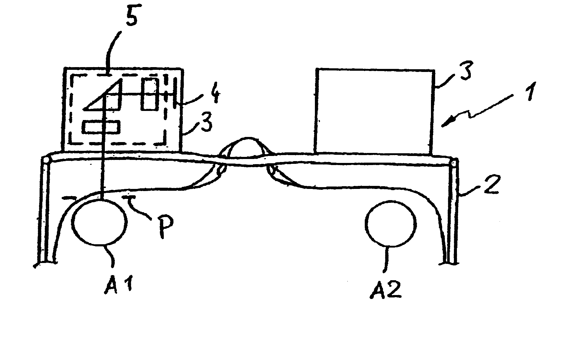
[0029]FIG. 1 shows a schematic view from above onto a user wearing the HMD device 1 according to the invention on his head. The HMD device comprises a spectacle-type frame 2 which is supported on the user's nose as well as on both of his ears (not shown). One image-generating means 3 each is attached to the frame 2 in front of each eye A1, A2 of the user. As shown in FIG. 1 for the left eye A1, the image-generating means 3 comprises an image element 4 which is a luminous microdisplay here, as well as imaging optics 5 by which the image generated by the image element 4 is imaged to infinity such that the user can perceive it with his left eye A1. For this purpose, the exit pupil P of the imaging optics 5 is located in the plane of the pupil of the eye A1.

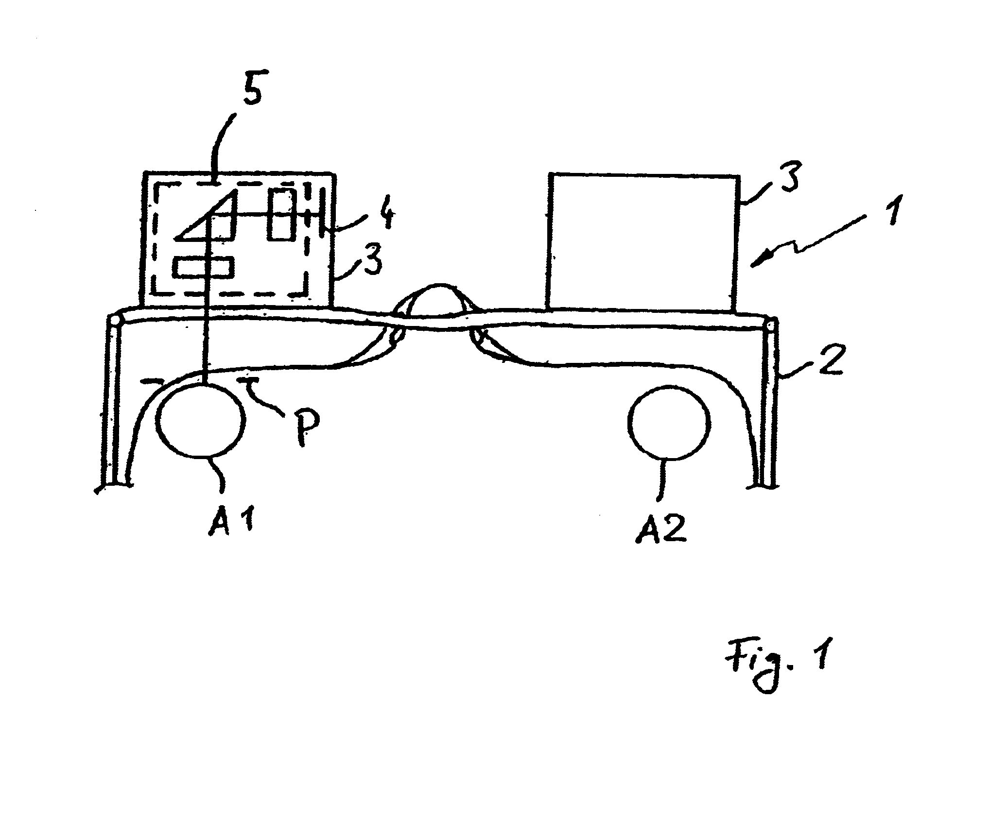
[0030]FIG. 2 shows an embodiment of the image-generating means 3 in greater detail. Arranged following the image element 4 are, in this order, a first optical group 6, which comprises a first lens 7 having negative refractive power a...


PUM


Abstract

An HMD device is provided, comprising an image element for generating an image and imaging optics projecting the image such that it is perceivable by a user wearing said HMD device, wherein said imaging optics comprise a first optical group including a first lens, which has negative refractive power, and a second lens, which has positive refractive power, a deflecting element arranged following the first optical group as well as a second optical group following the deflecting element, said second optical group comprising a third lens, and wherein, for correction of astigmatism and distortion, at least one surface of the first and second lenses is aspheric and, for correction of the spherical aberration, at least one surface of the third lens is aspheric.

Description

FIELD OF THE INVENTION[0001]The invention relates to an HMD device (Head mounted display device) comprising an image element for generating an image, and imaging optics projecting the image such that it is perceivable by a user wearing said HMD device.BACKGROUND OF THE INVENTION[0002]Difficulties in connection with such a known HMD device consist in that the exit pupil of the imaging optics has to be located such that the user wearing said HMD device can move his eye to this location, while at the same time, the diameter of the exit pupil has to be sufficiently large so that the user can perceive the entire image even during eye movements. Thus, the diameter of the exit pupil should be at least 8 mm and, at the same time, a field having a size of 25° should be provided, wherein said field and said exit pupil should allow good optical image quality to be realized. Such requirements can be met by providing additional lenses. However, an increase in the number of lenses is disadvantage...

Claims


Application Information

Patent Timeline
Patent Type & Authority Patents(United States)
IPC IPC(8): G02B27/01G02B27/00G02B3/04G02B3/02G02B27/02H04N5/74
CPCG02B3/04G02B27/0025G02B27/0172G02B2027/0178G02B2027/011G02B2027/0132
Inventor ACHTNER, BERTRAM
Owner CARL ZEISS AG
Why Eureka
Try Eureka