Structural foam

Inactive Publication Date: 2005-06-14
ZEPHYROS INC
View PDF199 Cites 73 Cited by
  • Summary
  • Abstract
  • Description
  • Claims
  • Application Information

AI Technical Summary

Problems solved by technology

This technique is not suitable for use in an electrocoat process commonly encountered in automotive applications.
Furthermore, the beam will only provide significant reinforcement along the axis of the beam.
This will result in uneven foaming and to non-uniform foam structures since on the underside the foam must raise the weight of the beam whereas expansion on the topside is free.
The former technique has the problem that it is not possible to perform the electrocoat over the entire s

Method used


Image

  • Structural foam
  • Structural foam
  • Structural foam

Examples


Embodiment Construction

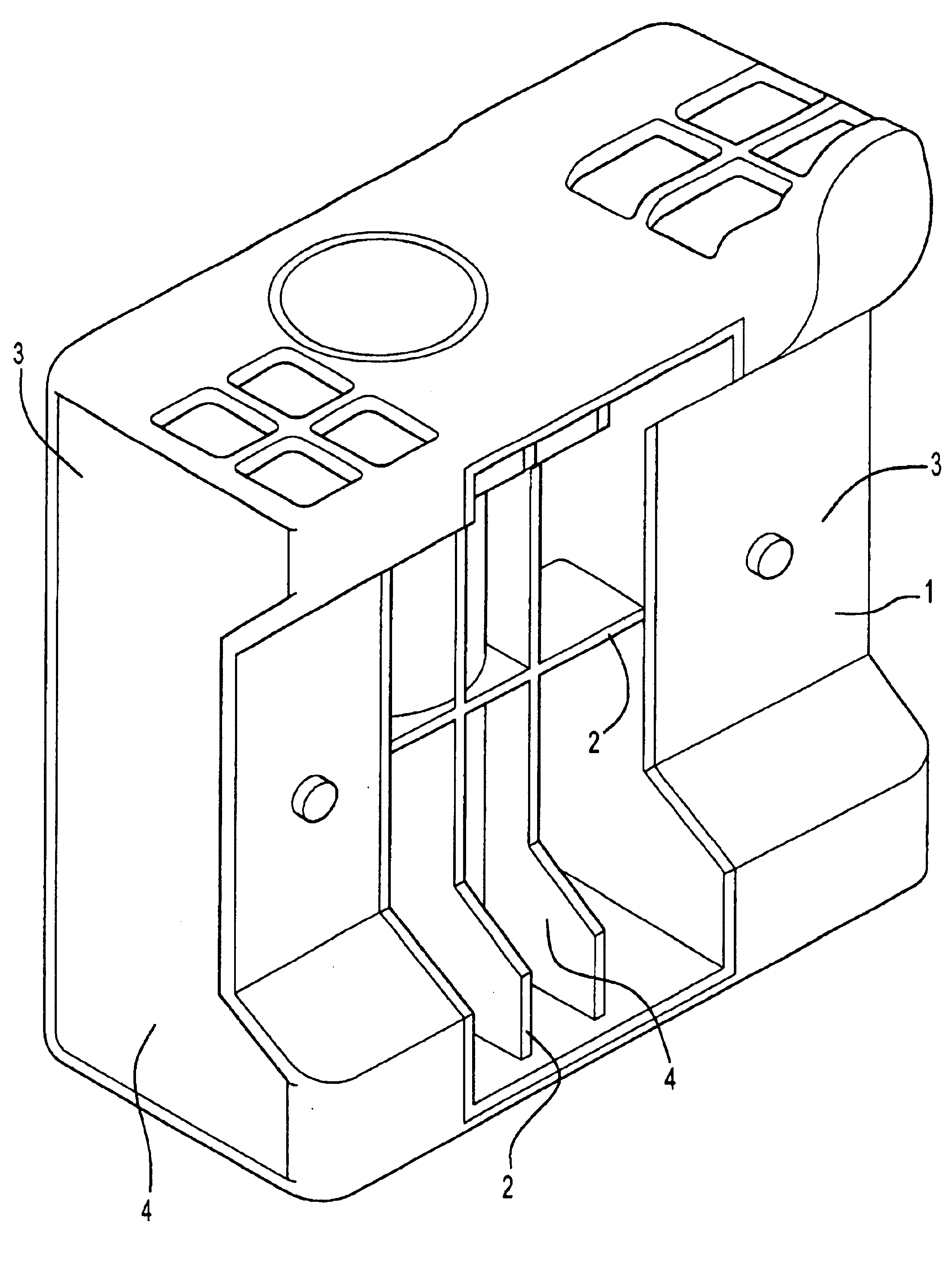
[0028]The present invention is illustrated by reference to the accompanying drawings in which FIG. 1 shows a moulding according to the present invention.

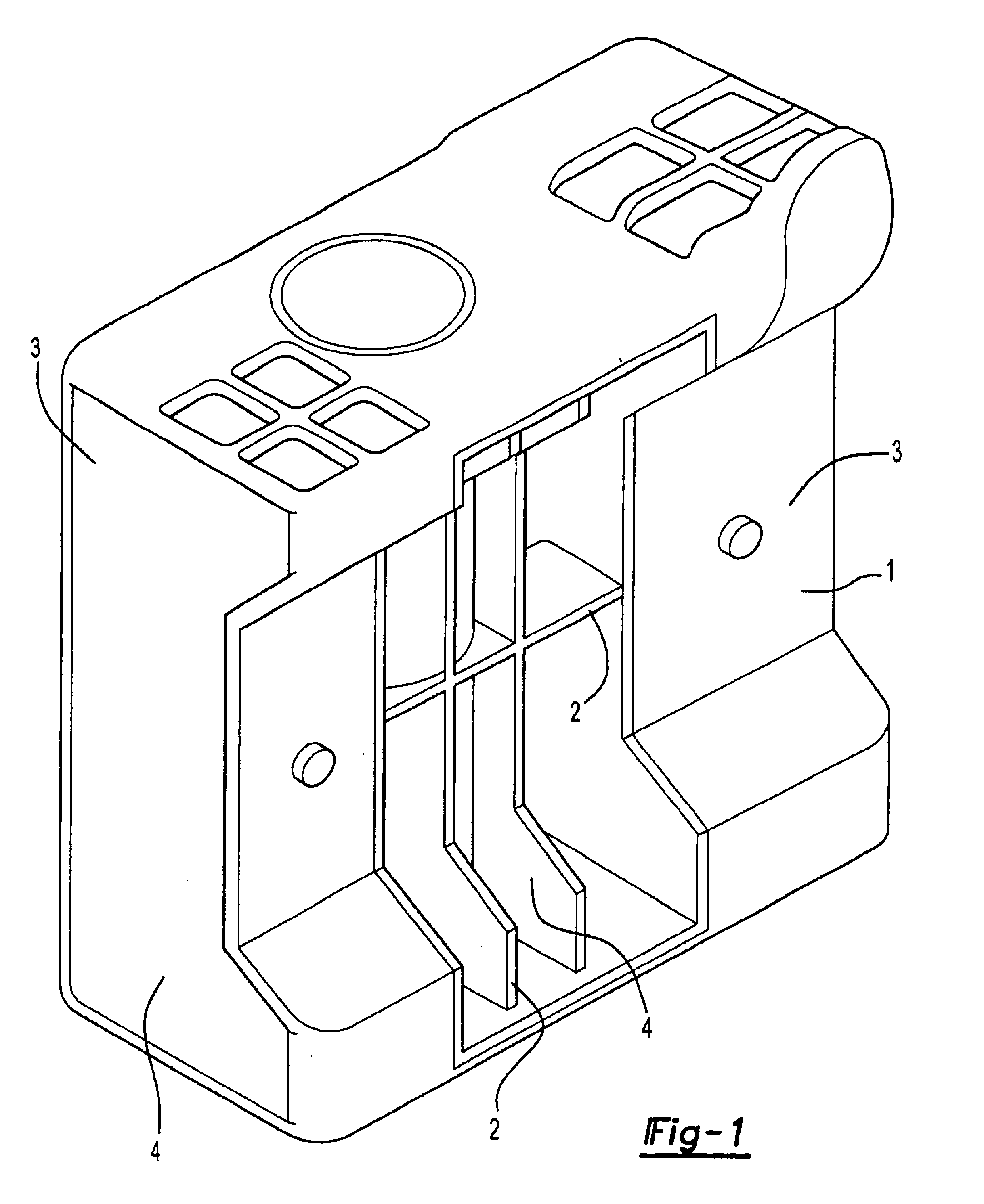
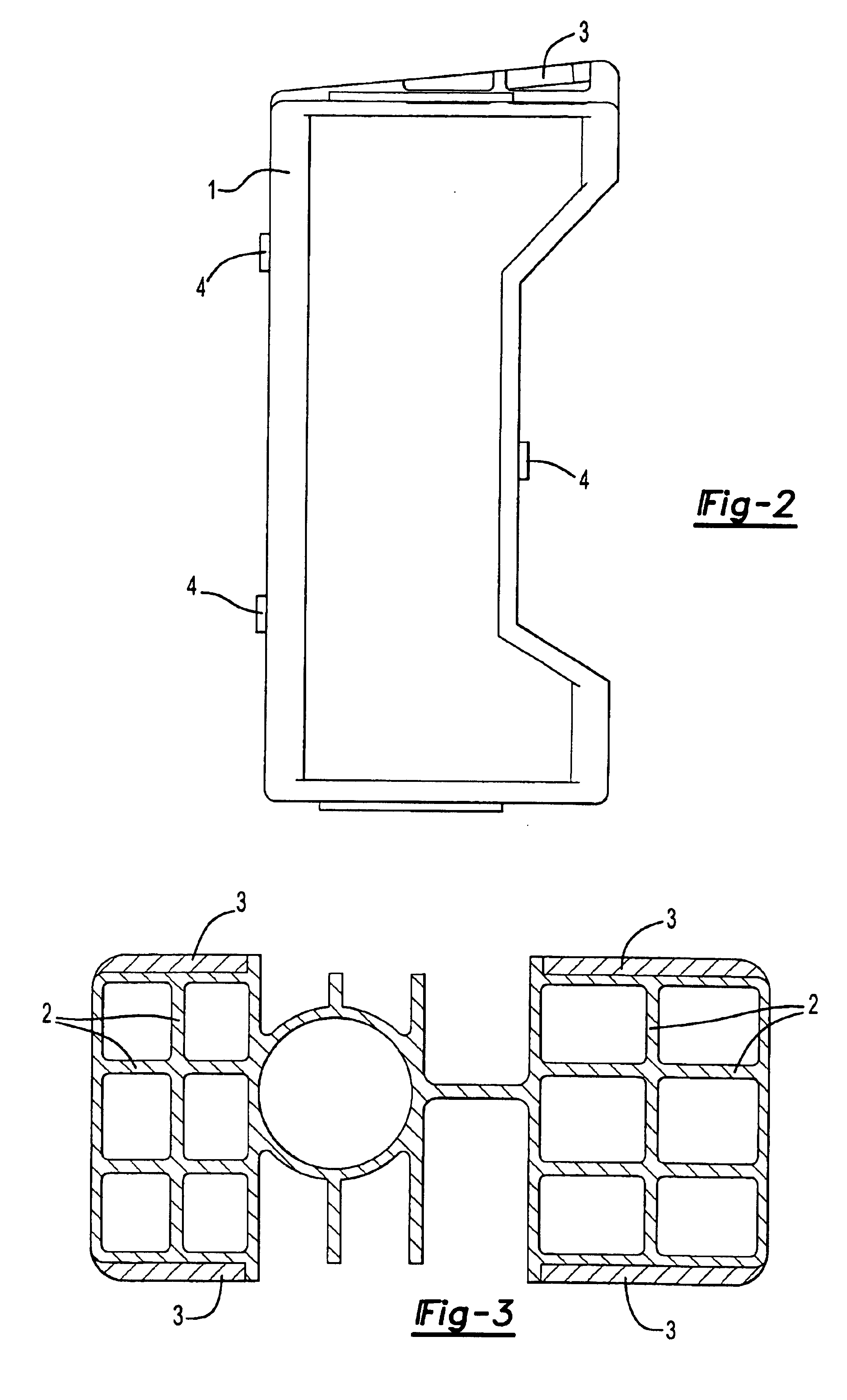
[0029]FIG. 1 is of a moulding designed to limit point mobility and prevent what is known as lozenging. The moulding consists of a reinforcing member 1 moulded to conform to the cross section of the front longitudinal section of a vehicle. The reinforcing member consists of a frame with transverse and longitudinal ribs 2 to provide compression strength and torsional resistance. The moulding has been over moulded at the two ends with layers of an expandable adhesive 3. FIG. 2 is an end elevation of the moulding showing the lugs 4 which will locate the moulding within the vehicle cross section. FIG. 3 is a cross section of the moulding shown in FIG. 1 illustrating the cellular structure.

[0030]FIG. 4 shows an alternate form of moulding which is suitable for resisting deformation particularly in the rear longitudinal section of a vehicle...


PUM

PropertyMeasurementUnit
Temperatureaaaaaaaaaa
Sizeaaaaaaaaaa

Abstract

A structural reinforcement for a hollow member comprising a rigid reinforcing member having a shape that substantially conforms to the cross section of the section of the hollow member to be reinforced with an expandable adhesive material over at least a portion of the surface of the rigid reinforcing member sufficient to bond the reinforcing member to at least two nonparallel internal surfaces of the structure.

Description

[0001]This application is a continuation of application No. 10 / 008,505 filed on Nov. 8, 2001, now U.S. Pat. No. 6,777,049, which claims priority from United Kingdom application number 0106911.1 filed Mar. 20, 2001. This application claims the benefit of the filing dates of both the aforementioned applications. U.S. application Ser. No. 10 / 008,505 and United Kingdom application Number 0106911.1.FIELD OF THE INVENTION[0002]The present invention relates to reinforcing materials and in particular to reinforcing materials that can be provided in hollow cross-sectional members particularly to provide reinforcement to improve the structural integrity of articles.BACKGROUND OF THE INVENTION[0003]The trends in motor vehicle design are towards lighter vehicles to improve fuel consumption. At the same time, auto manufacturers continue to demand more rigorous structural performance standards. The use of lighter materials such as aluminum to produce the hollow cross-sectional members that are us...

Claims


Application Information

Patent Timeline
IPC IPC(8): B62D29/00B60J7/00B60K37/00B60N2/00B60N3/00B60R99/00B62D21/15B62D25/00B62D33/00
CPCB62D21/15B62D25/00B62D29/002Y10T428/1324Y10T428/24322Y10T428/24182Y10T428/1376Y10T428/28Y10T428/24149Y10T428/233Y10T428/1355Y10T428/13Y10T428/24198
Inventor SHELDON, SIMONGALL, ERIC LEBOURDIN, JEAN PHILIPPEBIEBER, SERGE
Owner ZEPHYROS INC
Why Eureka
Try Eureka