Antenna, antenna device, and radio equipment

a technology of antenna device and antenna device, applied in the direction of resonant antenna, substantially flat resonant element, differential interacting antenna combination, etc., can solve the problems of reflection loss, deterioration of radiation efficiency, and large size of the first prior art antenna, so as to minimize directivity

Inactive Publication Date: 2005-06-14
RPX CORP
View PDF22 Cites 48 Cited by
  • Summary
  • Abstract
  • Description
  • Claims
  • Application Information

AI Technical Summary

Benefits of technology

[0053]Still yet another aspect of the present invention is an arrangement method of antennas that is an arrangement method of the antennas, comprising a step of aligning and arranging the plural antennas in a manner to conform a direction for minimizing directivity of each of the antennas on a horizontal plane.

Problems solved by technology

However, the first prior art antenna has the following drawback; intensifying the radiation in the horizontal direction of the antenna requires a two-dimensionally large ground conductor 211, which is against miniaturization of the monopole antenna.
Hence the first prior art antenna, which must be large in size because of its being difficult to be small two-dimensionally, is unsuitable.
These losses deteriorate the radiation efficiency.
The latter loss in particular leads to a reflection loss as the entire antenna array, and the reflected signal may reversely flow to each device connected to the antenna, thereby badly affecting the characteristics of each device.
Hence, the antenna array in the second prior art is unsuitable for miniaturization of an antenna.
The large-scale antenna array is unsuitable for the miniaturization of an antenna.
Hence the second prior art antenna, which must be large in size because of its being difficult to be small two-dimensionally, is also unsuitable.
It is further desired to install a monopole antenna inconspicuously not to be an eyesore; however, in the prior art antennas shown in FIGS. 36 through 39 the antenna elements project from the ceiling unsightly, and the structure of the first and second prior art antennas cannot satisfy the demand due to their failure to be miniaturized.

Method used


Image

  • Antenna, antenna device, and radio equipment
  • Antenna, antenna device, and radio equipment
  • Antenna, antenna device, and radio equipment

Examples


first embodiment

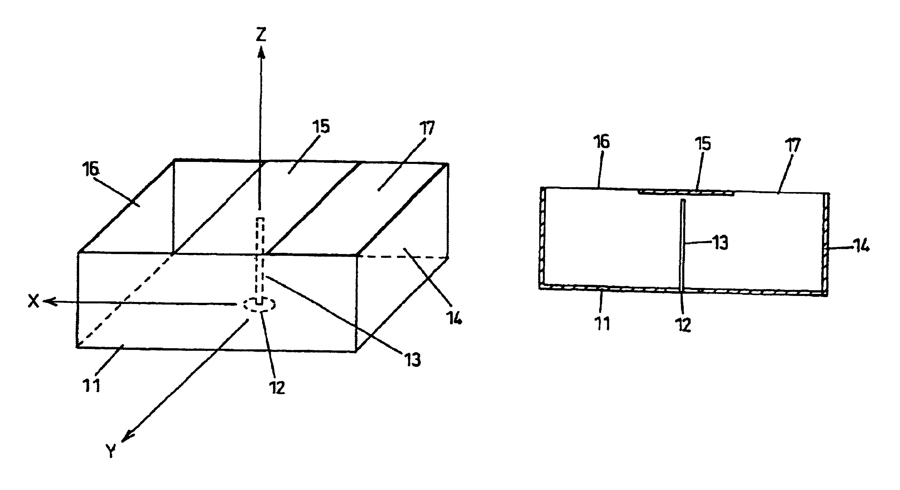
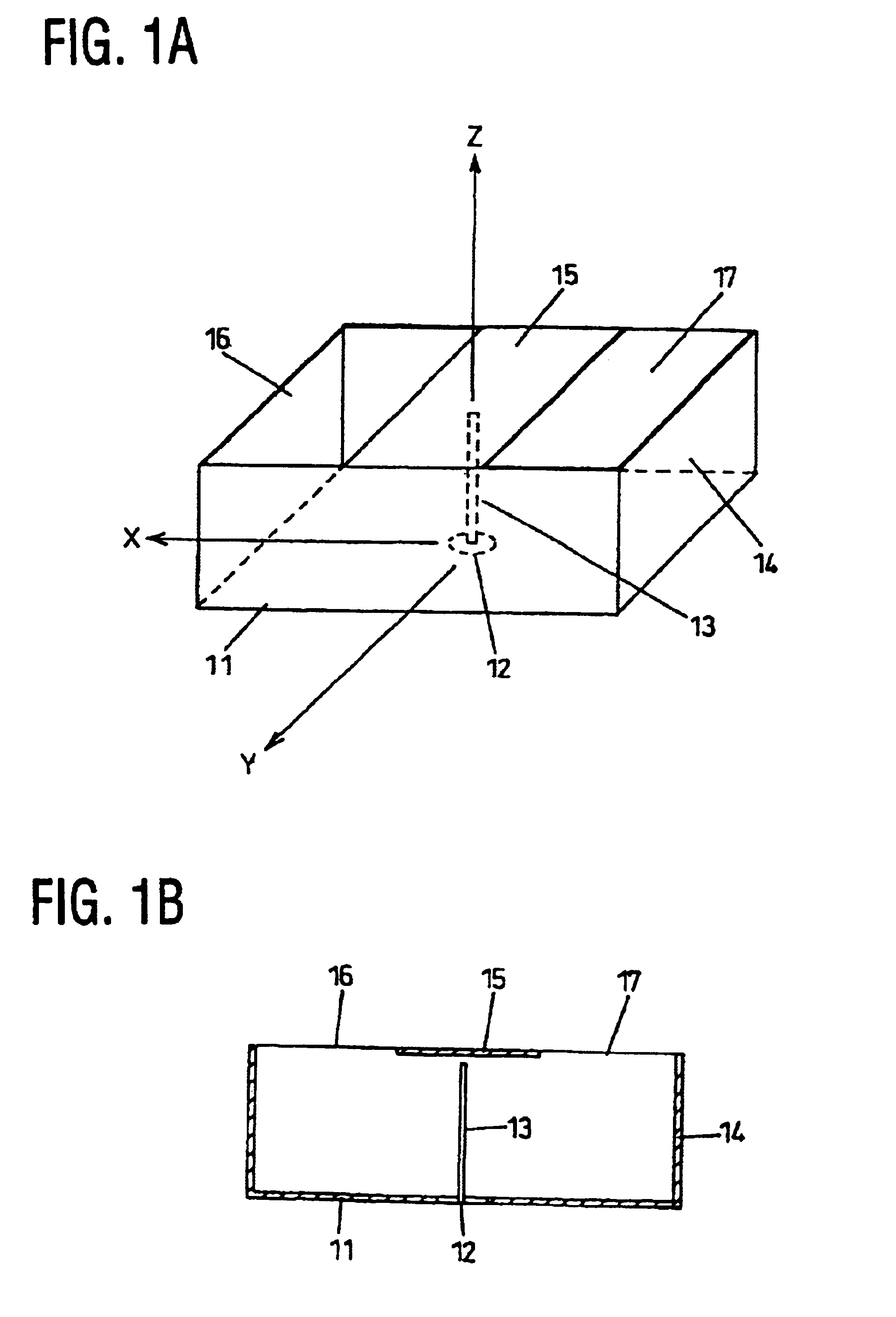
[0073]FIG. 1A is a schematic perspective view of a monopole antenna in the present invention;

[0074]FIG. 1B is a cross section of the monopole antenna in the first embodiment of the present invention;

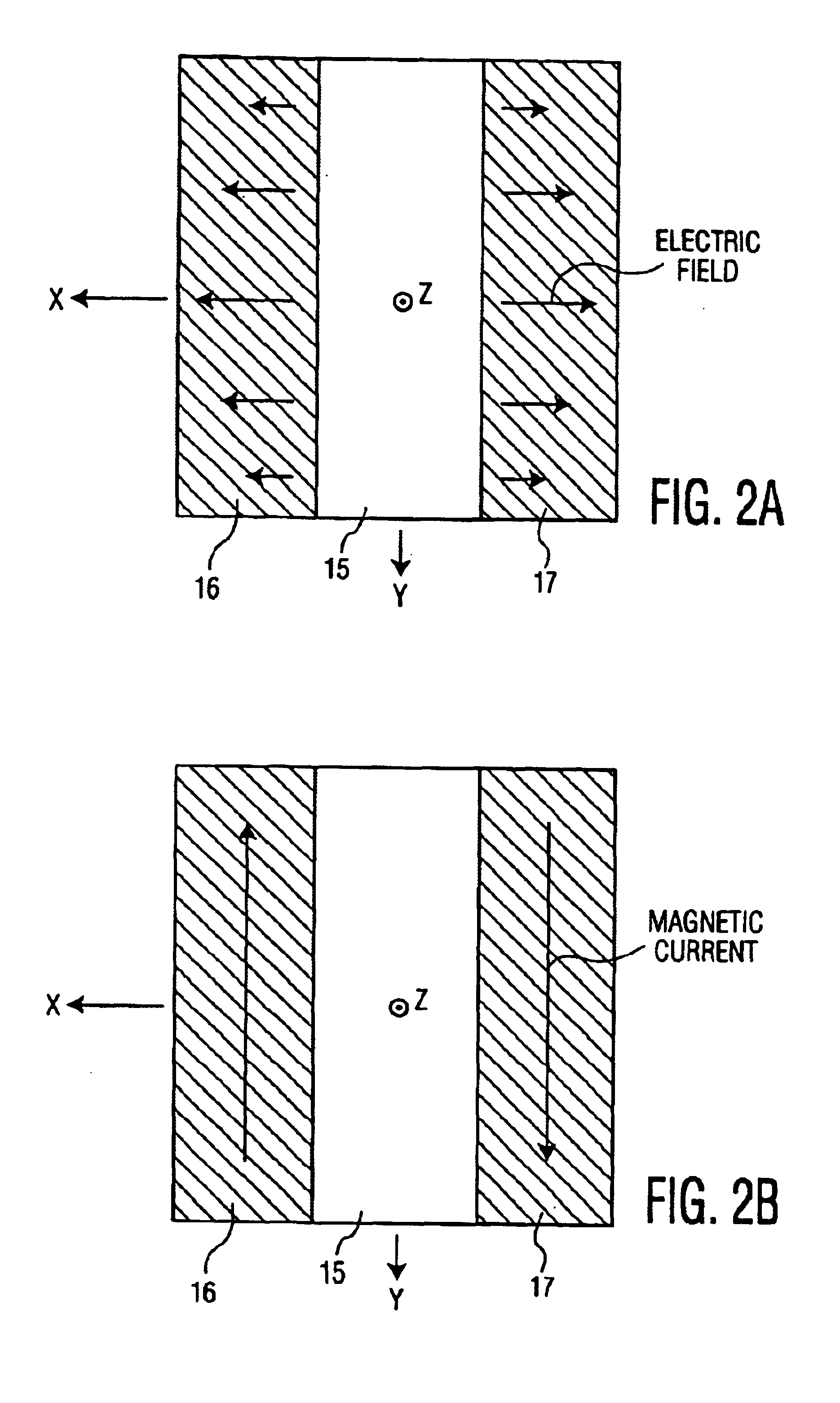
[0075]FIG. 2 is a drawing showing the operation principle of the first embodiment;

[0076]FIG. 3 is a schematic perspective view showing a working prototype of the first embodiment;

[0077]FIG. 4 is a diagram showing the radiation directivity of the working prototype of the first embodiment;

[0078]FIG. 5 is a graph showing the impedance characteristics of the working prototype of the first embodiment;

second embodiment

[0079]FIG. 6A is a schematic perspective view of a monopole antenna according to the present invention;

[0080]FIG. 6B is a cross section of the monopole antenna in the second embodiment of the present invention;

[0081]FIG. 7 is a schematic perspective view showing a working prototype of the second embodiment;

[0082]FIG. 8 is a diagram showing the radiation directivity of the working prototype of the second embodiment;

[0083]FIG. 9 is a graph showing the impedance characteristics of the working prototype of the second embodiment;

third embodiment

[0084]FIG. 10A is a schematic perspective view of a monopole antenna according to the present invention;

[0085]FIG. 10B is a cross section of the monopole antenna in the third embodiment of the present invention;


PUM


Abstract

An antenna has a conductive bottom member;a conductive side member; anda conductive member arranged in a space surrounded by the bottom member and the side member,wherein the conductive member is connected to a signal line for transmission and / or reception.

Description

DETAILED DESCRIPTION OF THE INVENTION[0004]1. Field of the Invention[0005]The present invention relates to an antenna, an antenna device, and a radio equipment that are used mainly in mobile communications, and in particular, to an antenna, which is optimal for an antenna for a base station, an antenna device, and a radio equipment.[0006]2. Related Art of the Invention[0007]Conventional technologies are shown in FIGS. 36 and 37.[0008]First, a first conventional example shown in FIG. 36 will be described. FIG. 36 shows an example of techniques with which the directivity of an antenna on a vertical plane is changed, and FIGS. 37A, 37B, and 37C each show an example of radiation directivity of a monopole antenna.[0009]FIG. 36 illustrates a ground conductor 211, a coaxial power supply part 212, and an antenna element 213. The antenna element 213 is connected to the coaxial power supply part 212 on the ground conductor 211. As an example, a case is shown, the case that a monopole antenna ...

Claims


Application Information

Patent Timeline
Patent Type & Authority Patents(United States)
IPC IPC(8): H01Q1/00H01Q13/10H01Q9/04H01Q19/00H01Q21/29H01Q13/18H01Q9/30H01Q21/00
CPCH01Q1/007H01Q9/0407H01Q9/0457H01Q21/29H01Q13/18H01Q19/00H01Q9/30
Inventor YAMAMOTO, ATSUSHIIWAI, HIROSHIOGAWA, KOICHI
Owner RPX CORP
Why Eureka
Try Eureka