Bayonet quick coupler

a quick coupler and bayonet technology, applied in the direction of flanged joints, fluid pressure sealed joints, sleeves/socket joints, etc., can solve the problems of insufficient assembly time of threaded couplers, inability to complete the support around the circumference of the coupler, and high propensity to damage, so as to avoid cross threading or inappropriate tightening, quick and easy attachment to and from the coupler, the effect of avoiding damage to delicate screw threads

Inactive Publication Date: 2005-06-21
FLUIDMASTER
View PDF16 Cites 52 Cited by
  • Summary
  • Abstract
  • Description
  • Claims
  • Application Information

AI Technical Summary

Benefits of technology

[0007]These disadvantages of the past are overcome with the present invention that provides an end fitting that can be quickly and easily attached to and detached from an assembly such as a valve body. Minimum effort is required and no special tools are needed. Damage to delicate screw threads, due to cross threading or inappropriate tightening, is avoided. The fitting can be attached without sliding it along the conduit and no separate retaining ring is required to hold it in place. In order to achieve these advantages, the bayonet quick coupler of the present invention has several objects.
[0011]Fourthly, each sector of the coupler has flanges that extend radially inwardly to block axial movement of a mating sector when assembled in a snap lock configuration. In general, a stopping flange is located at an end face of each of the sectors and engages an end face of another of the sectors to prevent relative axial movement between the sectors in first and second axial directions. In the preferred embodiment, each sector has an additional stopping flange also preventing relative axial movement as well as some radial movement between the sectors.

Problems solved by technology

Both of these systems have disadvantages.
For example, the split-ring lock system cannot provide a completed support around the circumference of the coupler.
Threaded couplers require an inordinate amount of time to assemble.
They also have a high propensity to damage, for example by cross threading and inappropriate tightening.

Method used


Image

  • Bayonet quick coupler
  • Bayonet quick coupler
  • Bayonet quick coupler

Examples


Embodiment Construction

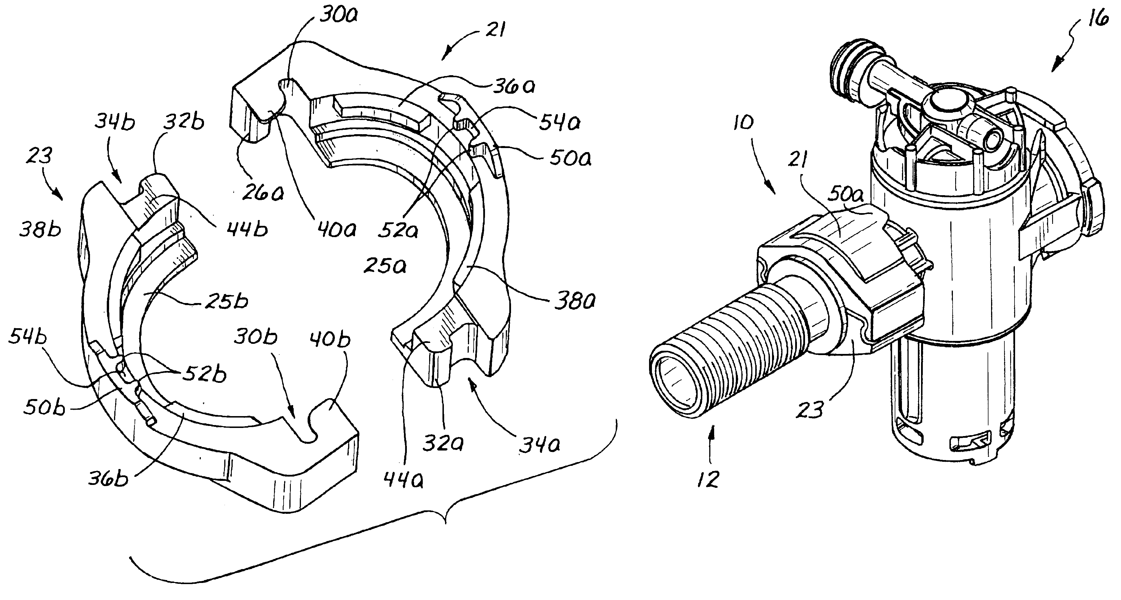
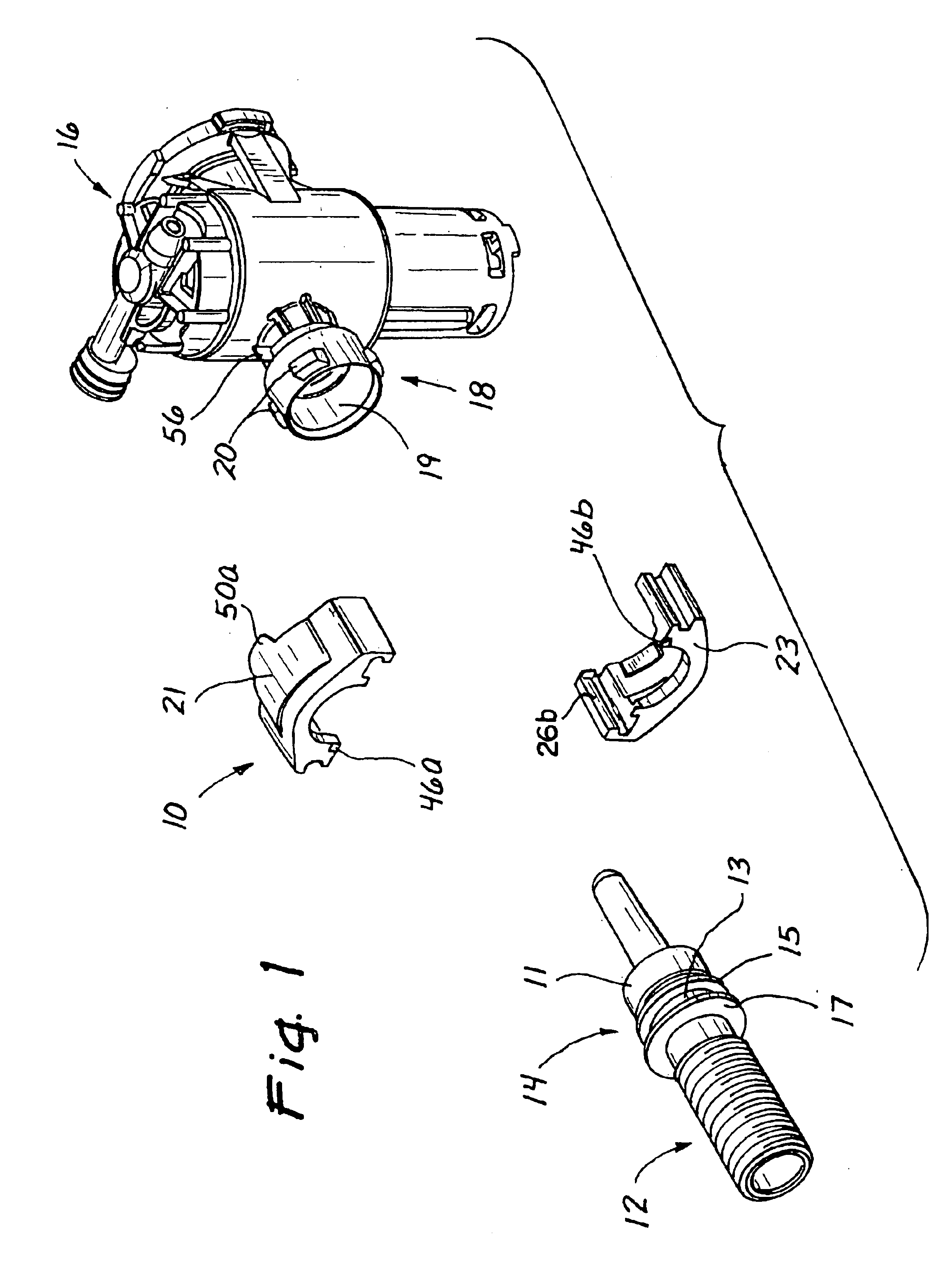
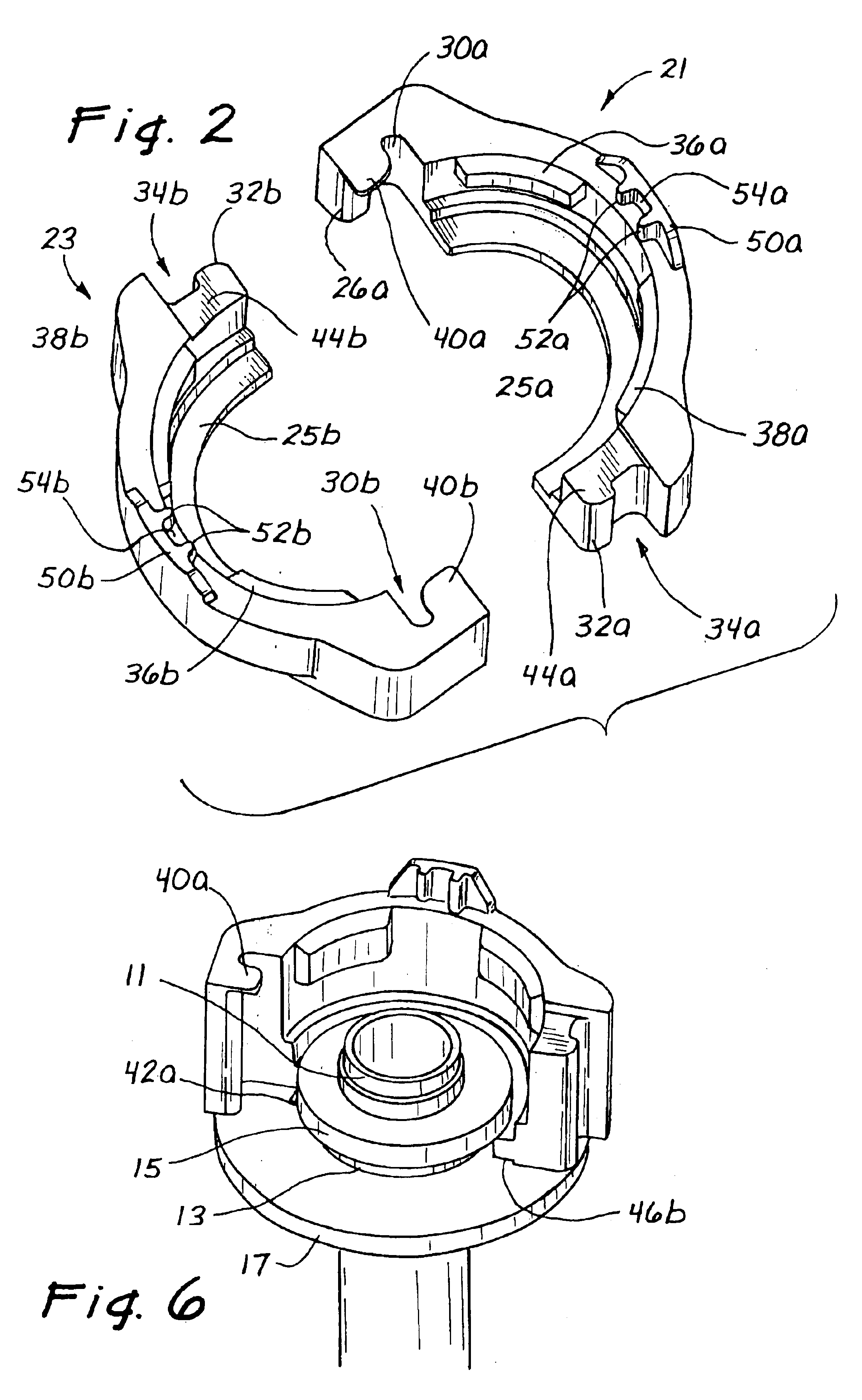
[0023]A first preferred embodiment of the quick coupler of the present invention is illustrated in FIG. 1 and designated by the reference numeral 10. This coupler 10 in the illustrated environment provides a device for coupling a shank assembly 12 to a valve assembly 16. The shank 12 has a first conduit 14. The valve assembly 16 has a second conduit 18 with a coupling 19 of the second conduit 18. The first conduit 14 is adapted for coupling to the second conduit 18 by the coupler 10.

[0024]The quick coupler 10 in this embodiment comprises two identical pieces or sectors 21 and 23 that combine to form a nut as shown in FIG. 2. Thus, the sectors 21 and 23 cooperate to form the single quick coupler 10 in the form of a nut or housing which connect the conduit 14 of the shank assembly 12 to the conduit 18 of the valve body 16, as shown n FIG. 5. The coupler 10 has opposite end faces and a annular hole extending along a central axis between the opposite end faces of the coupler. In the pre...


PUM


Abstract

A quick coupler formed of two identical sectors that snap lock together in a radially inward direction relative to a central axis of an annular hole passing through the coupler. The coupler is in the form of a nut or housing for surrounding the ends of two conduits that are to be coupled. The annular hole extends between opposite end faces and has structure near each end face. The structure at one end of the annular hole comprises a flange for retaining a first conduit when the sectors are snapped surroundingly snapped together on the end of the first conduit. The structure at the other end of the annular hole has circumferentially spaced lugs for cooperation with bosses on the second conduit in a bayonet quick coupling fashion. The combination of the coupler with first and second conduits having cooperating structure enabling the coupler to join the conduits in sealed fluid communication. The method of use of the combination comprises snap fitting the sectors onto an end of the first conduit by radially inward pressure.

Description

RELATED APPLICATION[0001]This application claims priority from U.S. patent application No. 60 / 244,076 filed Oct. 27, 2000 entitled “Bayonet Quick Coupler”.BACKGROUND OF THE INVENTION[0002]1. Field of the Invention[0003]This invention relates to end fittings and more specifically to end fittings adapted for coupling fluid conduits.[0004]2. Disclosure of the Prior Art[0005]Conventionally, a fluid conduit is coupled to a valve body or another fluid conduit by a threaded connector or a split-ring lock system. Both of these systems have disadvantages. For example, the split-ring lock system cannot provide a completed support around the circumference of the coupler. Furthermore it requires special tools to assemble and disassemble the ring.[0006]Threaded couplers require an inordinate amount of time to assemble. They also have a high propensity to damage, for example by cross threading and inappropriate tightening. In a threaded coupler design, a coupling nut may be used to attach a fluid...

Claims


Application Information

Patent Timeline
Patent Type & Authority Patents(United States)
IPC IPC(8): F16L37/00F16L37/252F16L37/248
CPCF16L37/248F16L37/252Y10S285/921
Inventor LE, TUAN
Owner FLUIDMASTER
Why Eureka
Try Eureka