Fishing device and method of attachment to a fishing line

Active Publication Date: 2014-02-11
BUHLER RONALD
View PDF18 Cites 4 Cited by
  • Summary
  • Abstract
  • Description
  • Claims
  • Application Information

AI Technical Summary

Benefits of technology

[0017]A further objective is to provide a fishing device that may be quickly a

Problems solved by technology

However, the prior art does not teach a fishing device that includes a conduit through the device, an annular groove around t

Method used


Image

  • Fishing device and method of attachment to a fishing line
  • Fishing device and method of attachment to a fishing line
  • Fishing device and method of attachment to a fishing line

Examples


Embodiment Construction

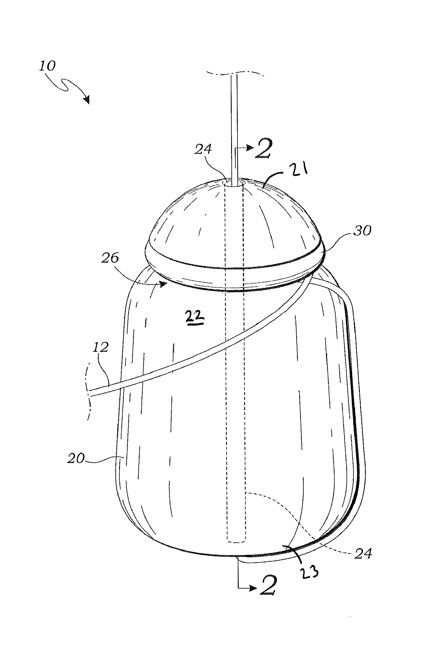
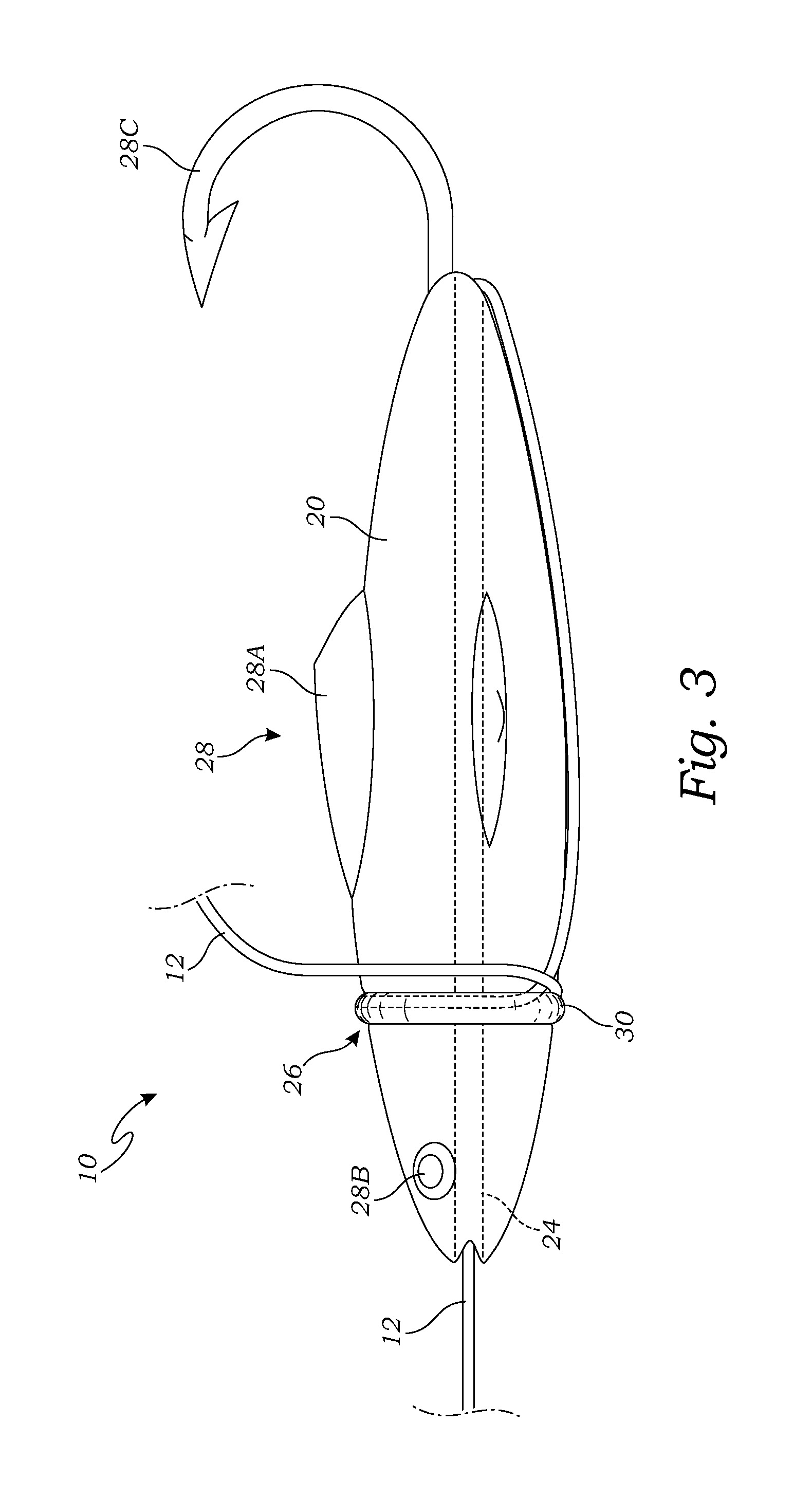
[0023]The above-described drawing figures illustrate the invention, a fishing device 10 adapted to be attached to a fishing line 12.

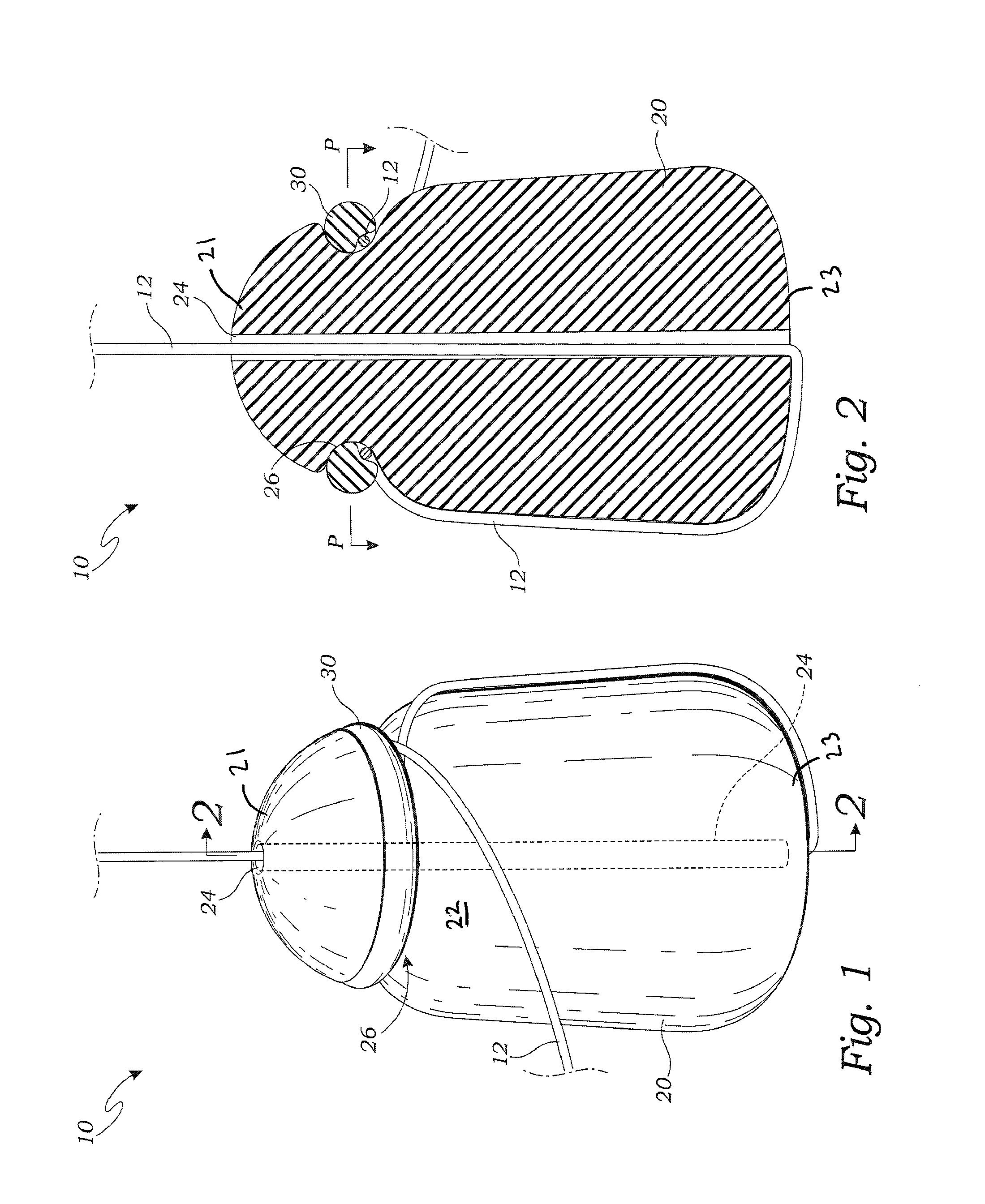
[0024]FIG. 1 is a perspective view of the fishing weight according to one embodiment of the present invention, wherein the fishing device 10 is a fishing weight. FIG. 2 is a sectional view thereof taken along line 2-2 in FIG. 1.

[0025]As shown in FIGS. 1 and 2, the, the fishing device 10 comprises a device body 20 having an outer surface 22, and a conduit 24 extending through the device body 20. The device body 20 of FIG. 1 is a metal fishing weight of standard construction. In alternative embodiments, the device body 20 may be made of other materials, and may be formed in alternative shapes, as is well known in the art.

[0026]As illustrated in FIG. 1, a groove 26 is formed in the outer surface 22 of the device body 20 and, extends at least partially around the device body 20. In the present embodiment, the groove 26 is an annular groove 26 that extends c...


PUM


Abstract

A fishing device has a device body having an outer surface, a conduit extending through the device body, an annular groove in the outer surface of the device body extending at least partially around the device body, and an annular wedge positioned around the device body and within the annular groove. In use, a fishing line is positioned through the conduit and wrapped completely around the annular groove. The annular wedge is adapted to lock the fishing line in the annular groove.

Description

CROSS-REFERENCE TO RELATED APPLICATIONS[0001]Not ApplicableBACKGROUND OF THE INVENTION[0002]1. Field of the Invention[0003]This invention relates generally to fishing devices, and more particularly to a fishing lure, weight, or similar device, that is adapted to be quickly, easily, and securely attached to and removed from a fishing line.[0004]2. Description of Related Art[0005]Various fishing devices such as lures and weights are known in the art, and teach a variety of methods of attachment of the device to a fishing line. Rogel, U.S. Pat. No. 5,031,351 for example, describes a two piece slip-sinker for use on fishing lines comprising a two sectional sinker adapted to separate at a linear disposed, axial central opening to receive a fishing line. The two piece slip-sinker is maintained as a unitary sinker by means of an elastomeric O-ring engaging a circumferential periphery channel disposed in the outer surface in the assembled slip-sinker and oriented transverse to the axial thr...

Claims


Application Information

Patent Timeline
IPC IPC(8): A01K95/02
CPCA01K91/04A01K95/02
Inventor BUHLER, RONALD
Owner BUHLER RONALD
Why Eureka
Try Eureka