Linear motion bearing segment

a technology of linear motion and bearings, applied in the direction of bearings, bearings, bearing shafts, etc., can solve the problems of reducing the load/life performance of the bearing assembly, difficult and expensive to achieve on the supporting structure, and difficult to manufacture efficiently

Inactive Publication Date: 2005-06-21
DANAHER MOTION
View PDF8 Cites 26 Cited by
  • Summary
  • Abstract
  • Description
  • Claims
  • Application Information

AI Technical Summary

Benefits of technology

[0020]The linear motion bearing assembly further includes an outer housing sleeve which substantially encloses all of the rolling element retainer structure. The housing sleeve is preferably formed of an engineering polymer and serves to protect the rolling element retainer and bearing rolling elements contained therein from ambient contamination.

Problems solved by technology

In addition this precise alignment also minimizes skewing forces acting on the bearing assembly, which skewing forces tend to reduce the load / life performance of the bearing assembly.
In such installations, considerable precision machining of the supported structure is necessitated which is difficult and expensive to accomplish on the supporting structures.
This structure, however, is difficult to efficiently manufacture because of the complex molds required.
Also, these ball retainers, prior to insertion into a mounting carriage or outer housing are necessarily open and thus exposed to ambient conditions and contaminants such as dust and dirt.
Such exposure could deleteriously affect the operation and life of the bearing assembly as well as the support structure on which it moves.
This configuration adds to the expense and complexity of the bearing.

Method used


Image

  • Linear motion bearing segment
  • Linear motion bearing segment
  • Linear motion bearing segment

Examples


Embodiment Construction

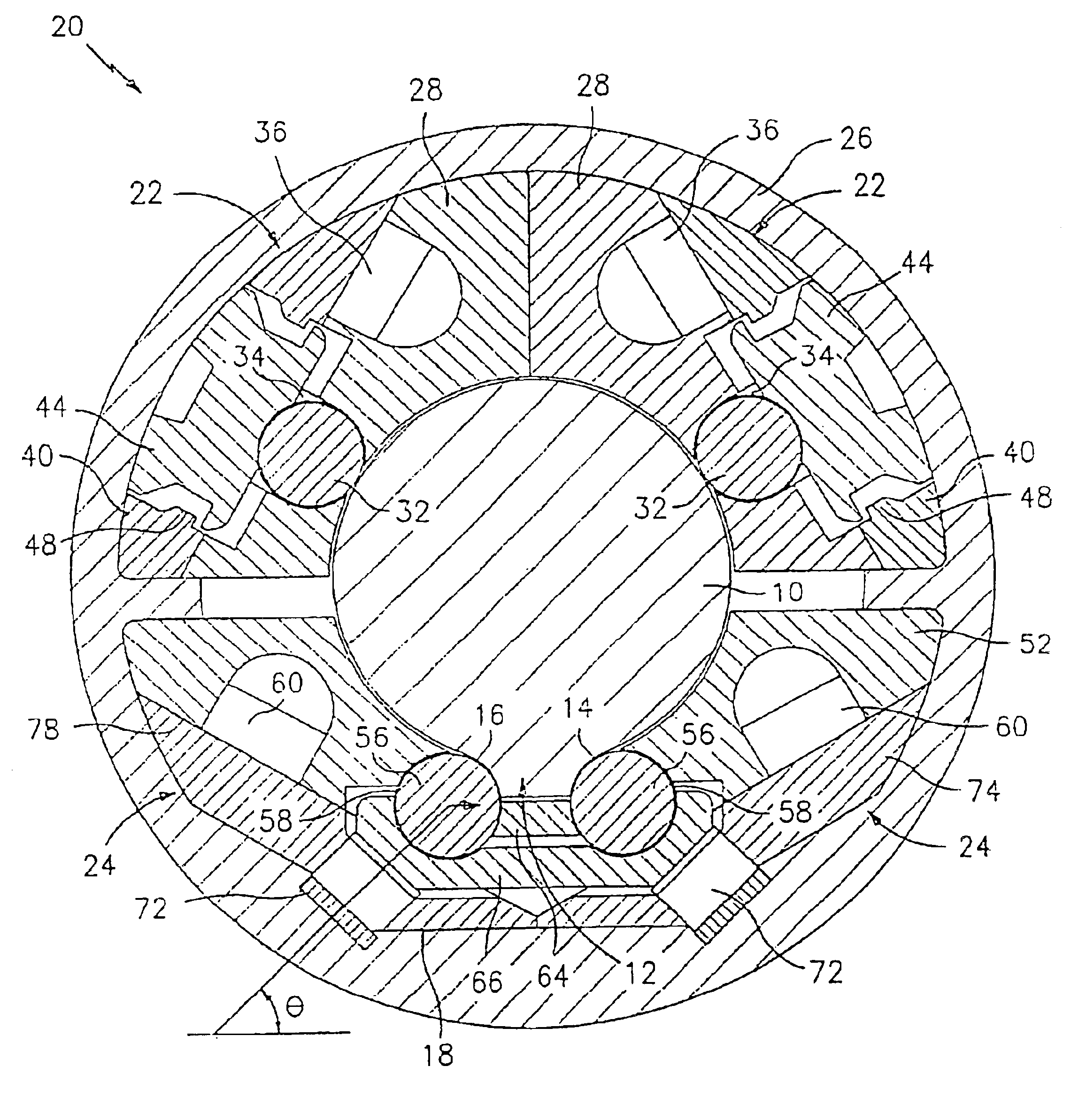
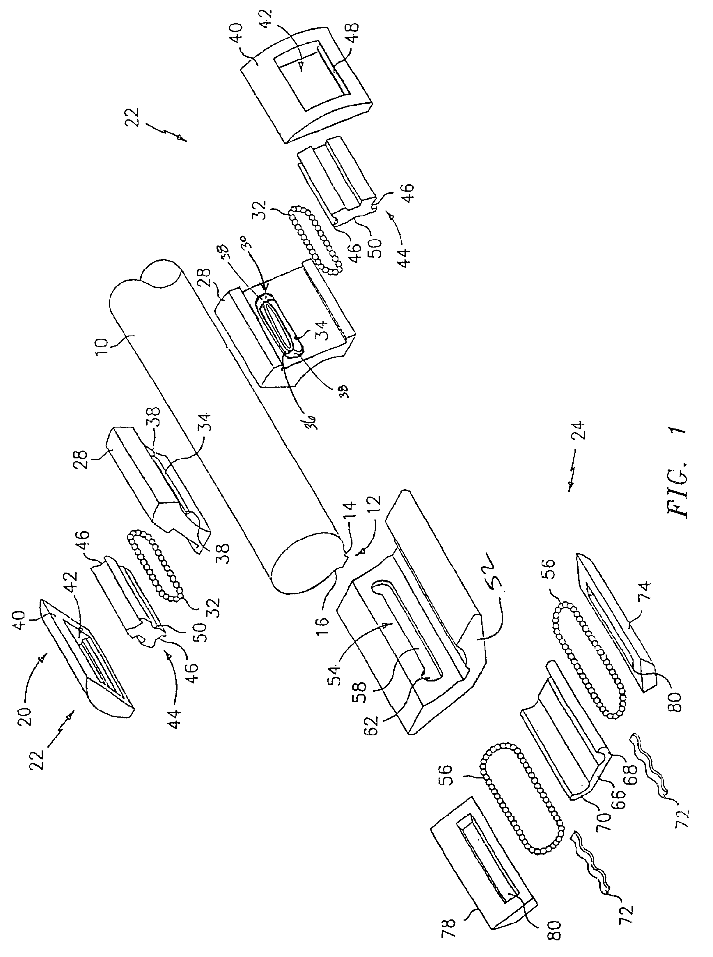
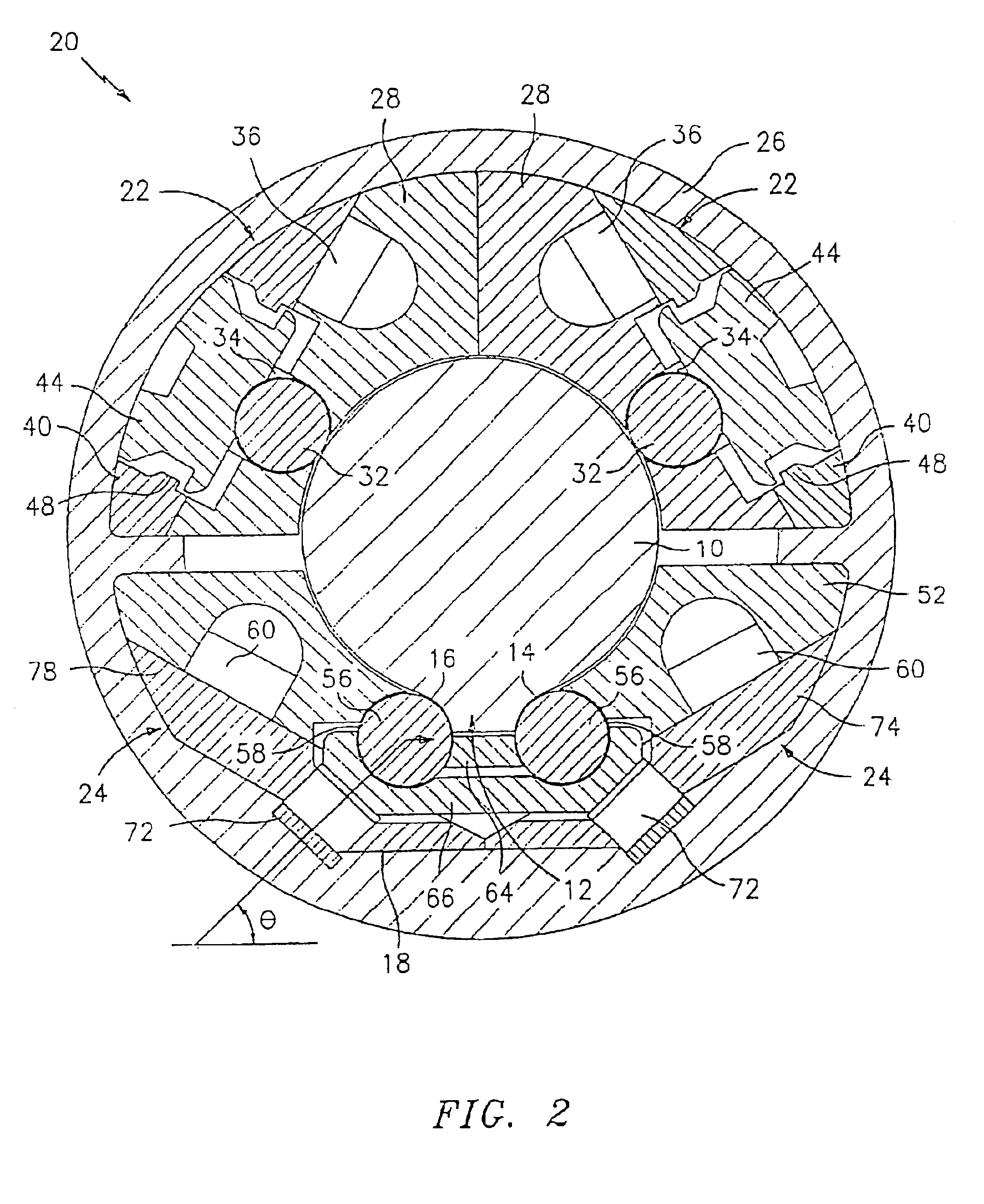
[0030]Referring now to the drawings, wherein like reference numerals identify similar structural elements of the subject invention, there is illustrated in FIGS. 1-5 a closed-type linear motion bearing segment constructed in accordance with a preferred embodiment of the present invention and designated generally by the reference numeral 20. As used herein, the term ball and rolling element are intended to be used interchangeably and encompass namely, ball bearings, roller bearings, needle bearings, axle bearings, etc. While a closed-type linear motion bearing segment is disclosed, it is envisioned that an open type linear motion bearing segment can be constructed in accordance with the present disclosure.

[0031]Linear motion bearing segment 20 is fabricated from a pair of individual quarter arcuate interengageable self-contained ball retainer segments 22 and a half arcuate interengageable self-contained ball retainer segment 24 all of which are supported in interengageable associatio...


PUM


Abstract

A linear motion bearing assembly (20) as provided for movement along a splined shaft (10). The rolling element retainer of the bearing assembly (20) is assembled from a plurality of arcuate interengageable self-contained rolling element retainer segments (22). Each of the rolling element retainer segments (22) includes at least one rolling element track (30) having a load bearing portion (34) and a return portion (36). At least one load bearing plate (44) is axially positioned in each segment and serves to receive and transmit loads from the bearing rolling elements (32) in the load bearing portion (34) of the ball tracks (30). An extended housing retainer structure encloses all of the exposed exterior surfaces of the rolling element retainer segments (22) and is configured and dimensioned to maintain the rolling element retainer segments (22) in position and to receive a load either directly or indirectly from the load bearing plates (44).

Description

CROSS REFERENCE TO RELATED APPLICATIONS[0001]The present application claims priority to U.S. provisional application Ser. No. 60 / 242,850 filed on Oct. 24, 2000, the entire contents of which are hereby incorporated by reference.BACKGROUND[0002]1. Technical Field[0003]The present invention relates to linear motion bearing and, more particularly, to linear motion bearing assemblies made up of bearing segments for longitudinal movement along a splined shaft.[0004]2. Background of Related Art[0005]The present invention is directed to an improved linear motion bearings assembly for use on a splined shaft. In particular, the improvements relate to biased linear motion bearing assemblies of the type which support a carriage or a pillow block for linear movement along an elongated splined shaft. These bearing assemblies can either be of the open type or the closed type.[0006]Typical linear rolling bearing assemblies include a series of rolling elements moving about a circulation path which c...

Claims


Application Information

Patent Timeline
Patent Type & Authority Patents(United States)
IPC IPC(8): F16C29/06F16C29/00
CPCF16C29/001F16C29/0697F16C29/069F16C29/123F16C2300/02F16C29/06
Inventor DALESSANDRO, FRANKCARLSON, SCOTTNG, ALISON
Owner DANAHER MOTION
Why Eureka
Try Eureka