Orthodontic distalizing apparatus

a technology of orthodontic devices and pusher pins, which is applied in the field of orthodontic distalizing devices, can solve the problems of causing displacement and the insufficient precision of the pusher pin on the tooth, and achieve the effect of avoiding displacement and avoiding dislocation

Inactive Publication Date: 2005-06-21
AMERICAN ORTHODONTICS
View PDF4 Cites 27 Cited by
  • Summary
  • Abstract
  • Description
  • Claims
  • Application Information

AI Technical Summary

Benefits of technology

[0016]According to a yet another aspect of an embodiment of the present invention, a second force generating element may be positioned intermedi

Problems solved by technology

The reaction force exerted by the pusher on the tooth being distalized is not discharged completely onto the basal gingiva and underlying bony support of the arch, but can also act at least partially on the tooth selected for anchoring of the framework, thus resulting in the risk of causing displacement of the latter as well.
The pusher pin therefor

Method used


Image

  • Orthodontic distalizing apparatus
  • Orthodontic distalizing apparatus
  • Orthodontic distalizing apparatus

Examples


first embodiment

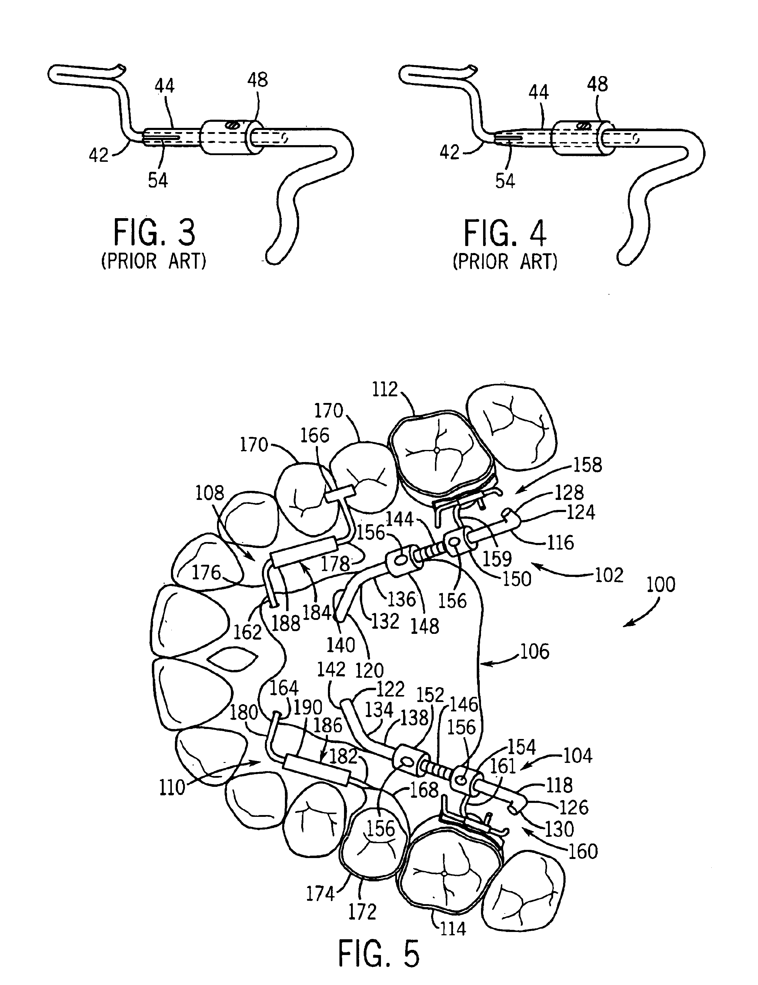
[0034]Referring initially to FIG. 5, an orthodontic distalizing apparatus 100 in accordance with the present invention is shown mounted to a maxillary jaw. As illustrated, apparatus 100 generally includes a pair of force generating elements 102 and 104, a force dissipating element 106 (e.g., a Nance button) configured for engaging the hard palate and / or alveolar ridge, and a pair of anchoring elements 108 and 110. Each force generating element is preferably positioned and oriented to apply a distalizing force to a respective molar 112, 114 in a direction substantially along a longitudinal axis of the dental arch and at a low level of the basal gingiva. As explained in the '520 patent, applying forces at this low level and orientation causes the tooth distalizing forces to pass as close as possible to the center points of resistance of the molar 112, 114 being distalized, which minimizes risk of any undesirable tilting occurring during distalization.

[0035]In the illustrated embodimen...

second embodiment

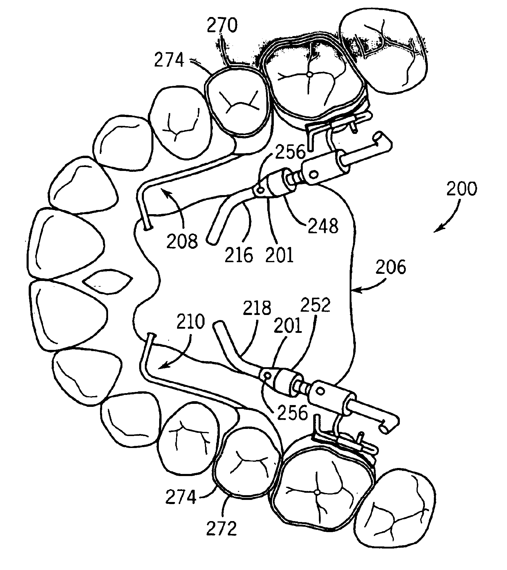
[0043]Referring now to FIG. 6, an orthodontic distalizing apparatus 200 is shown. For brevity, the description of distalizing apparatus 200 will be generally limited to its differences relative to distalizing apparatus 100 described above. For convenience, elements of distalizing apparatus 200 that are substantially similar to corresponding elements of distalizing apparatus 100 will be identified by the same reference numerals but preceded by a “2” instead of a “1”.

[0044]Distalizing apparatus 200 differs from distalizing apparatus 100 described above in that each anterior spring stop 248, 252 comprises a generally cone-shaped collar 201 and a set screw 256. As best seen in FIG. 7, cone shaped collar 201 comprises a cylindrical base portion 203 and a conical portion 205. Conical portion 205 includes a threaded bore 207 which extends approximately perpendicular to the conical outer surface 217 and is thus at an angle relative to a central bore 209 that extends through collar 201 for s...

third embodiment

[0046]Referring now to FIG. 9, an orthodontic distalizing apparatus 300 is shown. For brevity, the description of distalizing apparatus 300 will be generally limited to its differences relative to distalizing apparatus 100 described above. For convenience, elements of distalizing apparatus 300 that are substantially similar to corresponding elements of distalizing apparatus 100 will be identified by the same reference numerals but preceded by a “3” instead of a “1”.

[0047]Distalizing apparatus 300 differs from distalizing apparatus 100 described above in that force dissipating element 306 is in the form of an osseointegrated (e.g., subperiosteal or endosseous) implant 311. Implant 311, which resembles a button, is a relatively flat, disc-shaped fixture having a threaded aperture 313 for securing thereto the mesial ends 320, 322 of guiding elements 316, 318 or another transpalatal member. Implant 311 is known as an “indirect anchorage device,” which is a term of art given to implants ...


PUM


Abstract

An orthodontic distalizing apparatus comprises at least one force generating element positioned intermediate a force dissipating element secured to the hard palate and/or alveolar ridge and a first tooth (e.g., a molar) that is being distalized. The at least one force generating element is positioned to apply a distalizing force on the molar in a direction substantially along a longitudinal axis of the dental arch and at a low level of the basal gingiva. The at least one force generating element may be configured to prevent inadvertent disassembly thereof during installation, adjustment and/or conversion of the apparatus between an active and a passive state. In addition, the at least one force generating element may be configured to be reversibly convertible between an active state and a passive state without requiring removal of the device from the patient's mouth. Moreover, the at least one force generating element may be configured to provide a continuous activation force of substantially constant magnitude during distalization of the molar. The apparatus may also be constructed so that the force dissipating element is connected to at least one anchoring tooth by a slidable coupling that absorbs all reaction forces transmitted substantially along a direction of the longitudinal arch. A second force dissipating element may be positioned intermediate the force dissipating element and a second tooth (e.g., a bicuspid) to facilitate the closing of any gaps that are created following distalization of the molar. A method of converting an orthodontic distalizing apparatus between an active and a passive state is also provided.

Description

FIELD OF THE INVENTION[0001]The present invention relates to an orthodontic distalizing apparatus for correcting the relative position of the teeth.BACKGROUND OF THE INVENTION[0002]Orthodontic distalizing devices for correcting the relative position of the teeth of a dental arch are known. In such known devices of this kind, spring-loadable pusher means are generally arranged on the side opposite the lingual side of the dental arch. Moreover, the pusher means are interposed between the means for anchoring the framework to a tooth selected for that purpose and the means for fastening to the further tooth being distalized of the same branch of the dental arch. The reaction force exerted by the pusher on the tooth being distalized is not discharged completely onto the basal gingiva and underlying bony support of the arch, but can also act at least partially on the tooth selected for anchoring of the framework, thus resulting in the risk of causing displacement of the latter as well.[00...

Claims


Application Information

Patent Timeline
IPC IPC(8): A61C7/10A61C7/00
CPCA61C7/10A61C7/00
Inventor BOWMAN, STEVEN JAYTESTA, MAUROCARANO, ALDO
Owner AMERICAN ORTHODONTICS
Why Eureka
Try Eureka