Facsimile machine and image margin adjustment method

Inactive Publication Date: 2005-06-21
OKI DATA CORP
View PDF6 Cites 5 Cited by
  • Summary
  • Abstract
  • Description
  • Claims
  • Application Information

AI Technical Summary

Benefits of technology

[0005]An object of the present invention is to avoid both unnecessary overflow of printing margins and unnecessary reduction of image size in a facsimile machine.
[0006]Another object of the invention is to avoid moire patterns when an image is enlarged or reduced in a facsimile machine.
[0009]Horizontal repositioning and width reduction avoid the overflow of printing margins.

Problems solved by technology

One problem is that, since different margins may be set in different facsimile machines, the printing margins set at the receiving facsimile machine do not necessarily match the scanning margins set at the transmitting facsimile machine.
If either the left or right printing margin is larger than the corresponding scanning margin, part of the scanned image of each page will overflow the printing margin and be lost when the page is printed.
A conventional solution to this problem is to reduce the width of each page slightly when it is printed, but this often causes pages to be reduced unnecessarily.
This is undesirable, because the reduction process can create dropouts or otherwise degrade the quality of the printed page.
If the page includes natural images such as photographs, the reduction process tends to produce annoying moire patterns.

Method used


Image

  • Facsimile machine and image margin adjustment method
  • Facsimile machine and image margin adjustment method
  • Facsimile machine and image margin adjustment method

Examples


first embodiment

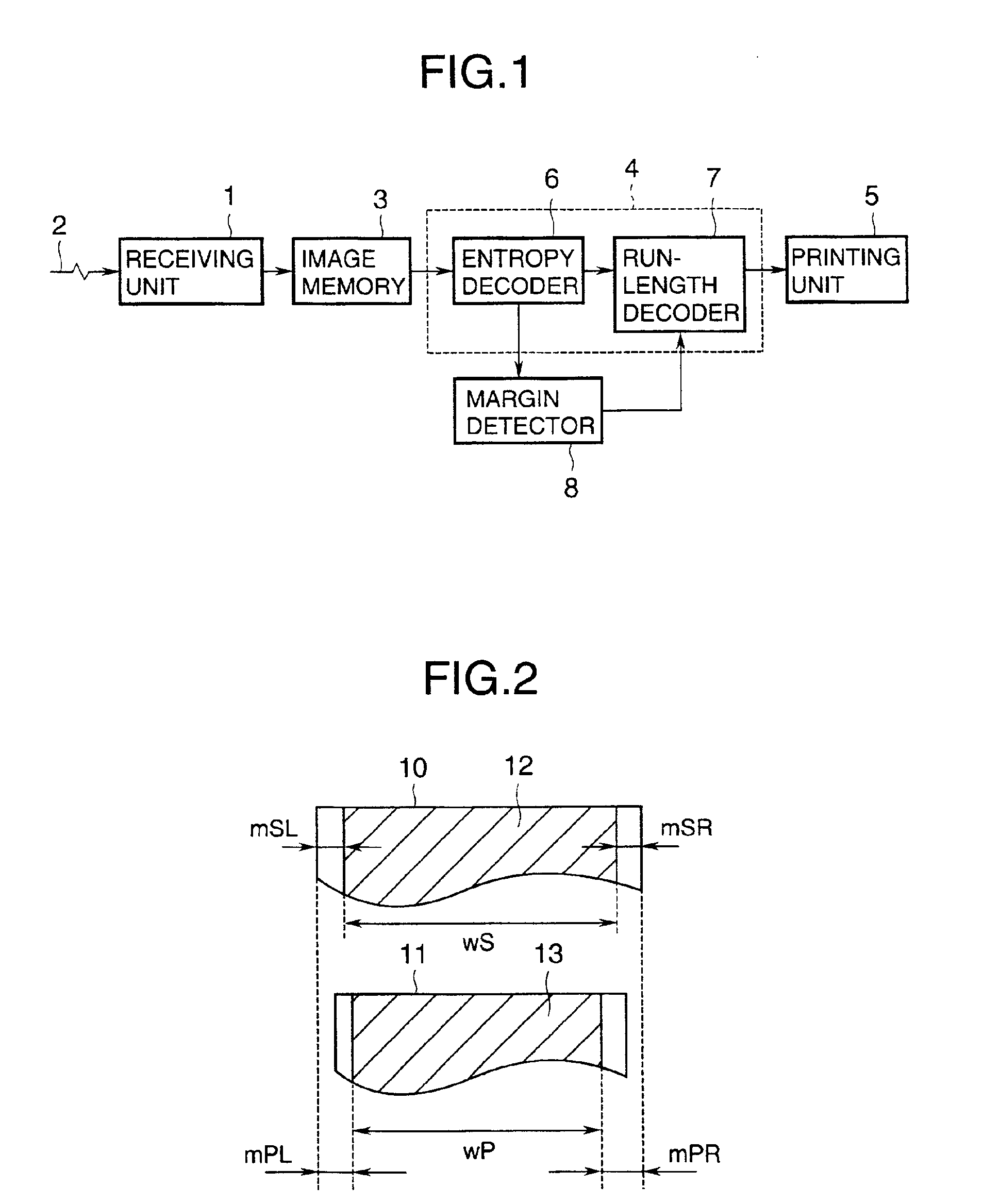
[0028]Referring to FIG. 1, the first embodiment is a facsimile machine comprising a receiving unit 1 coupled to a communication line 2, an image memory 3 coupled to the receiving unit 1, an image data decoding unit 4 coupled to the image memory 3, and a printing unit 5 coupled to the image data decoding unit 4. The image data decoding unit 4 comprises an entropy decoder 6 and a run-length decoder 7, and is coupled to a novel margin detector 8. The run-length decoder 7 also functions as an adjustment unit.

[0029]The facsimile machine in FIG. 1 receives and prints a transmitted document as follows.

[0030]The receiving unit 1 stores the document data, received from the communication line 2, in the image memory 3. The document data have been coded by run-length coding and entropy coding at the transmitting facsimile machine (not visible), and are stored in coded form. The entropy decoder 6 reads the coded document data from the image memory 3 and performs entropy decoding to obtain run-le...

third embodiment

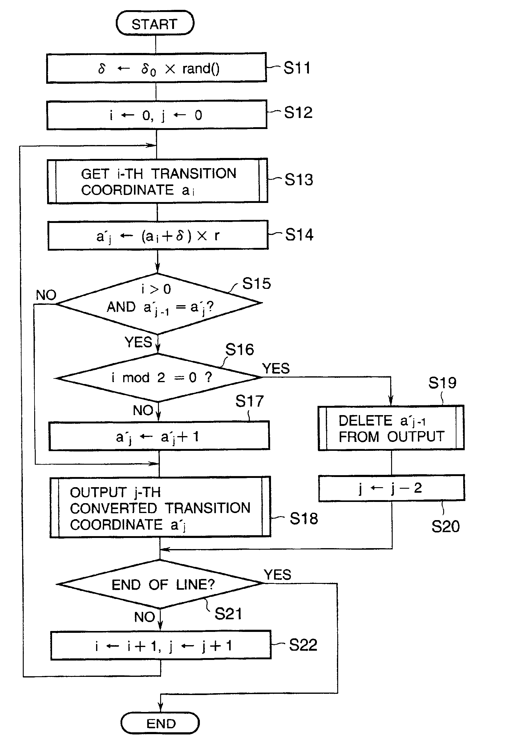
[0068]Natural images, and other images that generate moire patterns when zoomed, usually have more black-white transitions per scanning line than do text and line drawings, which do not generate moire patterns. Accordingly, when zooming a page, the run-length decoder 7 in the third embodiment counts the number n of transitions in each scanning line and compares this number n with a predetermined threshold N. If n is less than N, the scanning line is assumed to belong to a text or line-art part of the page, and is zoomed with a fixed offset value. If n is equal to or greater than N, the scanning line is assumed to be part of a natural image, and is zoomed with a randomized offset value.

[0069]For each scanning line, the procedure shown in FIG. 8 is followed. First, a random offset value e is calculated by multiplying a random number rand( ) by a fixed variance coefficient E (step S31). The random number rand( ) is between zero and one (0≦rand( )32). If there are fewer than N transitio...


PUM


Abstract

A facsimile machine detects transition points in image data, and adjusts the image data accordingly. Preferably, the image data are run-length data, from which image margins are detected, and the image data are adjusted to avoid overflow of printing margins. The adjustment may include horizontal repositioning and zooming. In zooming, an offset is preferably added to avoid moire patterns.

Description

BACKGROUND OF THE INVENTION[0001]The present invention relates to a facsimile machine, more particularly to the adjustment of margins in image data in a facsimile machine.[0002]To allow for skewed pages and other irregularities in paper transport, conventional facsimile machines leave predetermined blank left and right margins both in scanning and in printing documents. Conventional facsimile machines also allow the margins to be adjusted in a preset manner by the manufacturer or user. In addition, many conventional facsimile machines have a zoom function enabling received pages to be enlarged or reduced in size when printed.[0003]One problem is that, since different margins may be set in different facsimile machines, the printing margins set at the receiving facsimile machine do not necessarily match the scanning margins set at the transmitting facsimile machine. If either the left or right printing margin is larger than the corresponding scanning margin, part of the scanned image ...

Claims


Application Information

Patent Timeline
IPC IPC(8): B41J21/00G06T3/40H04N1/393H04N1/387H04N1/40H04N1/38
CPCH04N1/3875H04N1/38
Inventor SATO, JUNJI
Owner OKI DATA CORP
Why Eureka
Try Eureka