Heated milk supply system for livestock

a technology for heating milk and livestock, applied in the field of heating milk supply system for livestock, can solve the problems of lowering the temperature of the liquid, and not being as palatable for small, baby animals,

Inactive Publication Date: 2005-06-28
SOPPE JOHN
View PDF27 Cites 13 Cited by
  • Summary
  • Abstract
  • Description
  • Claims
  • Application Information

AI Technical Summary

Problems solved by technology

Although systems of this type assure a constant supply of the liquid feed to the animals, when the ambient air temperature is low and remains low for a...

Method used


Image

  • Heated milk supply system for livestock
  • Heated milk supply system for livestock

Examples


Embodiment Construction

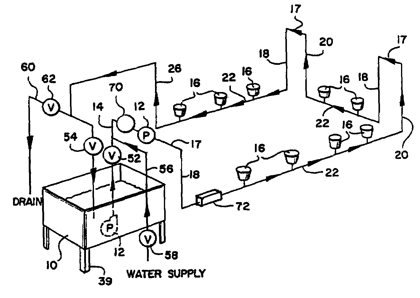
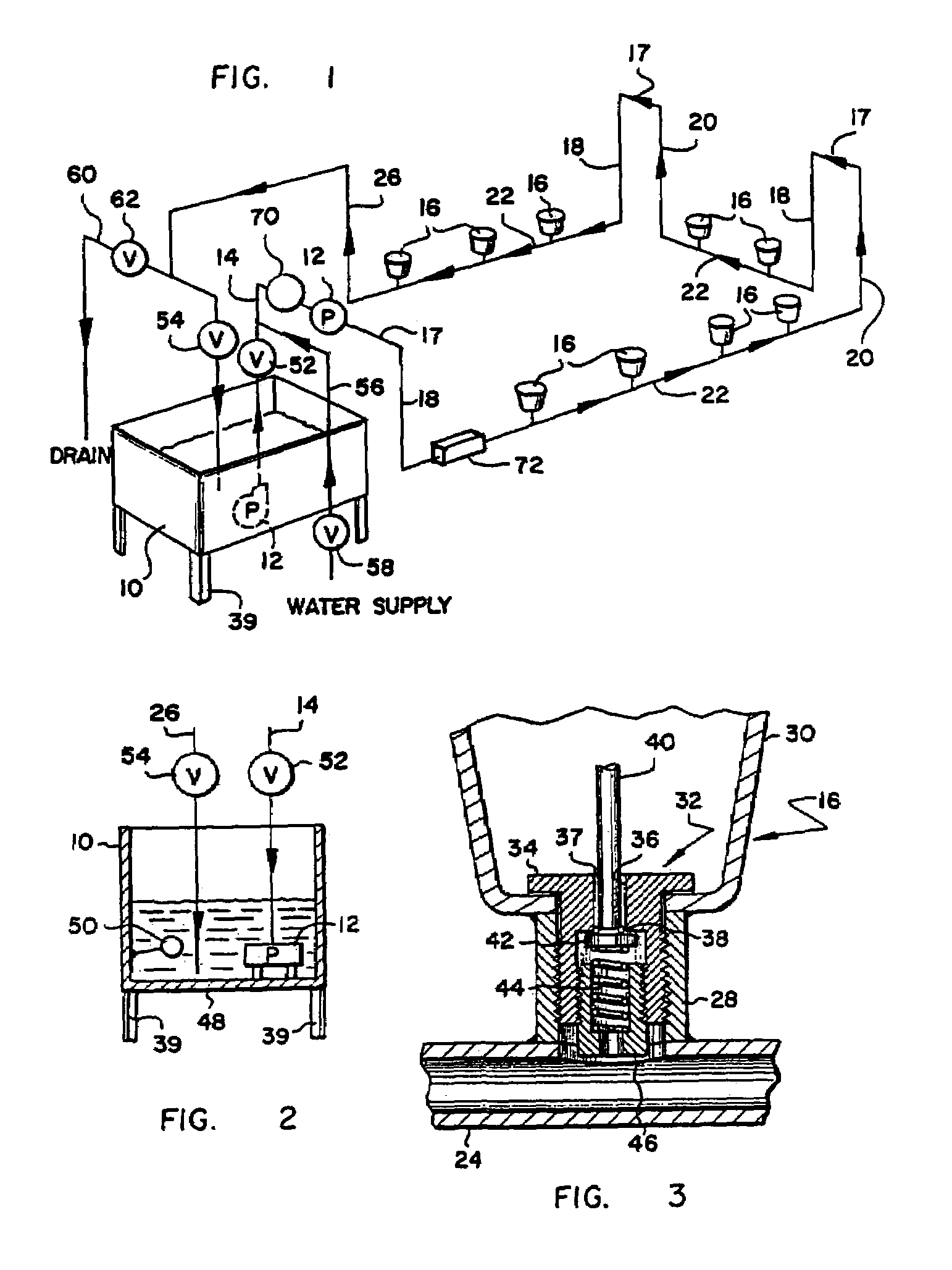
[0009]Referring first to FIG. 1, the system of the invention provides for delivery of the liquid feed, such as milk, from a source contained in a supply tank 10. The milk in tank 10 is circulated throughout the system by a circulating pump 12 through a supply line 14. In FIG. 1, pump 12 is shown as a submersible pump and also as being located outside of tank 10. Location of the pump 12 is preferably outside the tank 10 in supply line 14 for reasons explained more fully hereinafter. Supply line 14 follows a pattern consisting of a plurality of vertical loops as shown in FIG. 1. In other words, the supply line 14 carries the milk out of the tank 10 usually upwardly to an upper level several feet above the floor level of the building in which the system is installed, and then around the building at this upper level while dropping downwardly to the drinker units 16 positioned at or near the bottom of each of the vertical loops. The number and location of the vertical loops will depend i...


PUM


Abstract

A system for supplying heated milk or other liquids to individual drinkers from which animals, particularly baby pigs, can drink on a need basis by actuating a valve in the drinker that allows the milk to flow into the drinker. The system has a plurality of drinkers within a closed system in which the milk is supplied from a reservoir, heated to a minimum predetermined temperature range and pumped to each drinker which is positioned so that milk is continuously circulated through the drinker any time the circulating pump is running. This not only keeps the heated milk from spoiling, but it also prevents the drinkers from becoming clogged and permits the entire system to be cleaned in place.

Description

BACKGROUND OF INVENTION[0001]Livestock producers frequently utilize automatic feeding systems to assure that the animals, especially small animals, are always supplied with adequate feed for healthy and rapid growth. In the case of baby pigs, the feed is frequently supplied in a liquid form, usually milk or a milk replacer. The liquid feeding systems that are presently in use provide the liquid to individual drinker units from a supply tank, the drinker units permitting the animals to drink on a need basis by actuating a valve that allows the milk to flow into the unit. In presently known systems, each drinker unit is connected by a vertical line to an overhead trunk or supply line, the milk being supplied to each drinker unit. An example of such a system is shown in my U.S. Pat. No. 5,115,764. Although systems of this type assure a constant supply of the liquid feed to the animals, when the ambient air temperature is low and remains low for an extended period of time, the temperatu...

Claims


Application Information

Patent Timeline
IPC IPC(8): A01K5/00A01K5/02A01K7/06A01K7/00A01K7/02
CPCA01K5/0216A01K7/06A01K7/027
Inventor SOPPE, JOHN
Owner SOPPE JOHN
Why Eureka
Try Eureka