Ink ribbon cartridge with leaf spring and method of assembling the same

a technology of leaf spring and cartridge, which is applied in the direction of inking apparatus, printing mechanisms, instruments, etc., can solve the problems of slackening and partially unwinding of the ink ribbon from the spool

Inactive Publication Date: 2005-06-28
EASTMAN KODAK CO
View PDF20 Cites 18 Cited by
  • Summary
  • Abstract
  • Description
  • Claims
  • Application Information

AI Technical Summary

Problems solved by technology

This is done to prevent the spool from being rotated accidentally, such as might occur when the ca

Method used


Image

  • Ink ribbon cartridge with leaf spring and method of assembling the same
  • Ink ribbon cartridge with leaf spring and method of assembling the same
  • Ink ribbon cartridge with leaf spring and method of assembling the same

Examples


Embodiment Construction

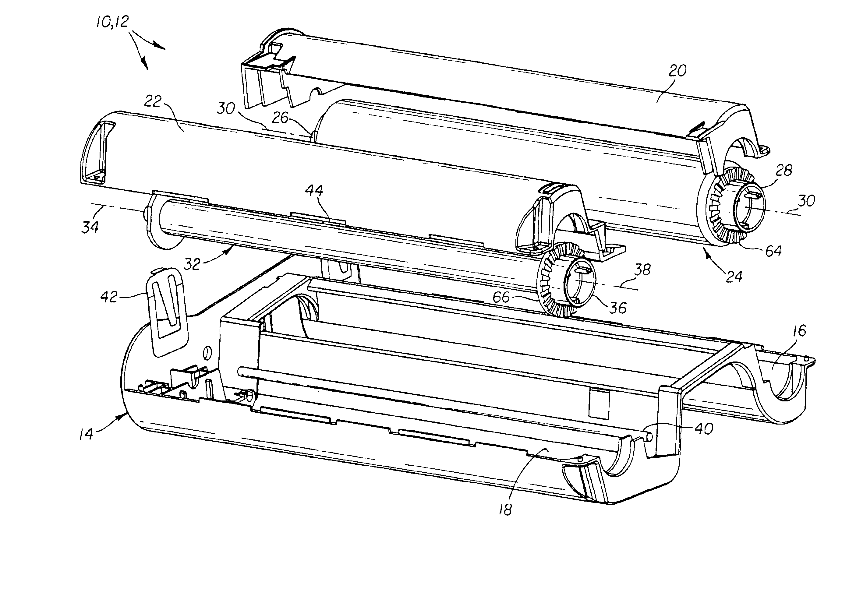
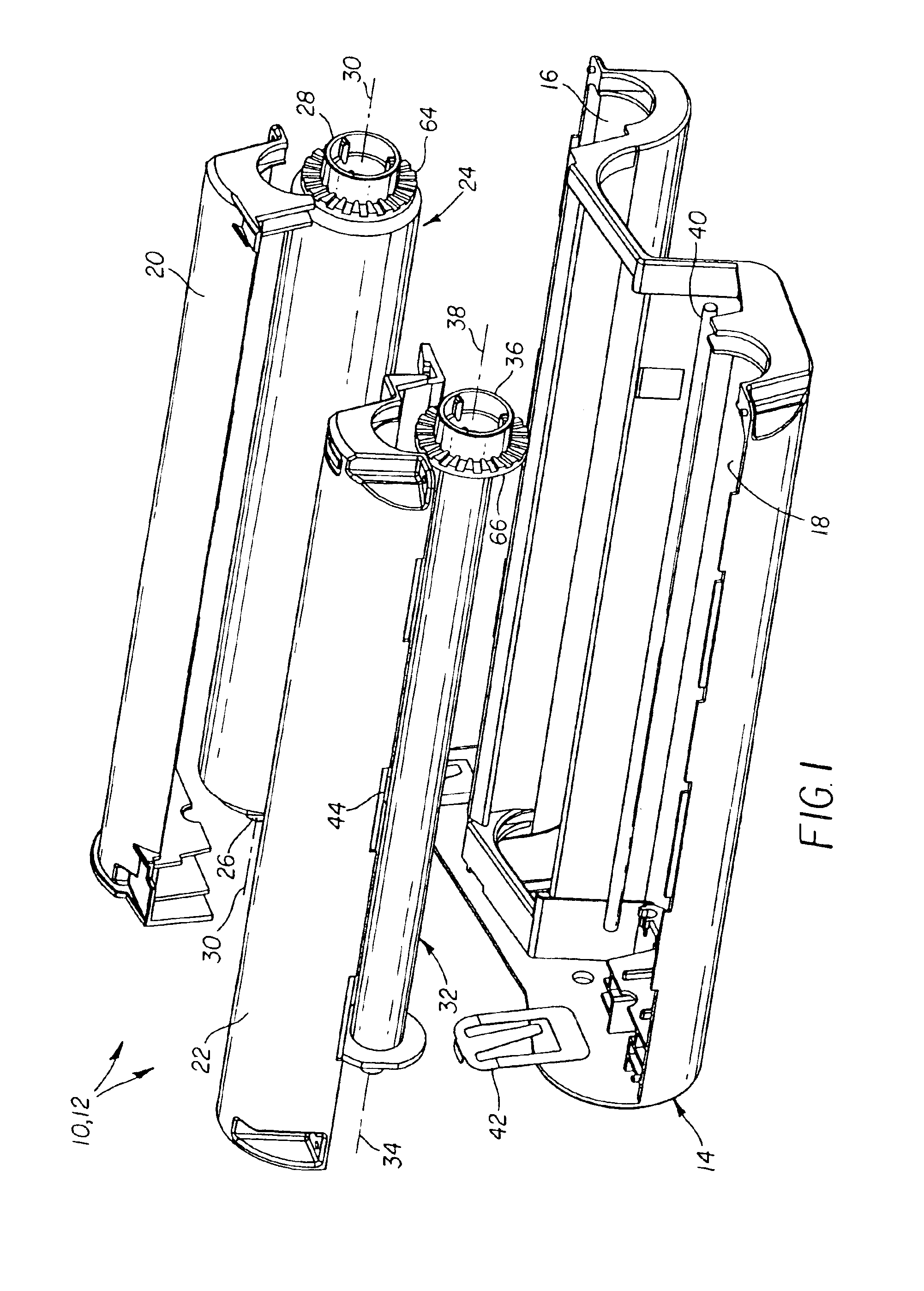
[0013]Because the features of an ink ribbon cartridge such as may be used in a thermal printer are generally known, the description which follows is directed in particular only to those elements forming part of or cooperating with the invention. It is to be understood, however, that other elements not disclosed may take various forms known to persons of ordinary skill in the art.

[0014]FIG. 1 shows an ink ribbon cartridge 10 having a (plastic) cartridge shell or housing 12 that comprises a housing-half 14, which includes parallel semi-cylindrical chambers 16 and 18, and also respective semi-cylindrical covers 20 and 22 for the two chambers. An ink ribbon supply (plastic) spool 24 having opposite hub ends 26 and 28 and an axis of rotation 30 resides in the chamber 16, and an ink ribbon take-up (plastic) spool 32 having opposite hub ends 34 and 36 and an axis of rotation 38 resides in the chamber 18. The ink ribbon supply and take-up spool 24 and 32 are essentially identical, and are i...


PUM


Abstract

A method of assembling an ink ribbon cartridge comprises inserting a leaf spring having a mounting frame and a flat spring finger that longitudinally extends from the mounting frame, beginning at an opening in the mounting frame, and at an acute angle from the opening, into a housing-half to position the spring finger pointing at the acute angle into the housing-half, and inserting an ink ribbon spool having opposite hub ends and a rotation axis into the housing-half, laterally relative to the rotation axis, to cause one of the hub ends to depress the spring finger at least partially into the opening, whereby the spring finger will urge the spool in one direction along the rotation axis.

Description

FIELD OF THE INVENTION[0001]The invention relates generally to an ink ribbon cartridge such as may be used in a thermal printer and to a method of assembling the same, and in particular to an ink ribbon cartridge that has a leaf spring for biasing an ink ribbon spool axially to deter accidental rotation of the spool in the cartridge.BACKGROUND OF THE INVENTION[0002]Ink ribbon cartridges for a thermal printer are well known. Typically, the ink ribbon cartridge includes an ink ribbon supply spool and an ink ribbon take-up spool that are rotationally supported parallel to one another in a cartridge housing. The ink ribbon has a repeating series of three different color sections or patches such as a yellow color patch, a magenta color patch, and a cyan color patch. Also, there may be a transparent colorless laminating section or patch immediately after each cyan color patch.[0003]Often, a compression-type spring is interposed between an inner wall at one side of the cartridge housing an...

Claims


Application Information

Patent Timeline
IPC IPC(8): B41J17/32B41J33/52B41J35/28B41J17/02B65H16/06
CPCB41J17/32B41J35/28B41J33/52
Inventor LYSIAK, PAUL A.SATO, HIROSHI
Owner EASTMAN KODAK CO
Why Eureka
Try Eureka