Check valve with vibration prevention function

a technology of check valve and function, applied in the field of check valve, can solve the problem of pressure pulsation amplified by the vibration of the ball

Inactive Publication Date: 2005-06-28
ADVICS CO LTD
View PDF13 Cites 15 Cited by
  • Summary
  • Abstract
  • Description
  • Claims
  • Application Information

AI Technical Summary

Benefits of technology

[0008]In view of the foregoing situation, an object of the present invention is to prevent or inhibit vibration of a valve body from amplifyin...

Problems solved by technology

This causes a problem in which the vibra...

Method used


Image

  • Check valve with vibration prevention function
  • Check valve with vibration prevention function
  • Check valve with vibration prevention function

Examples


first embodiment

[0033](First Embodiment)

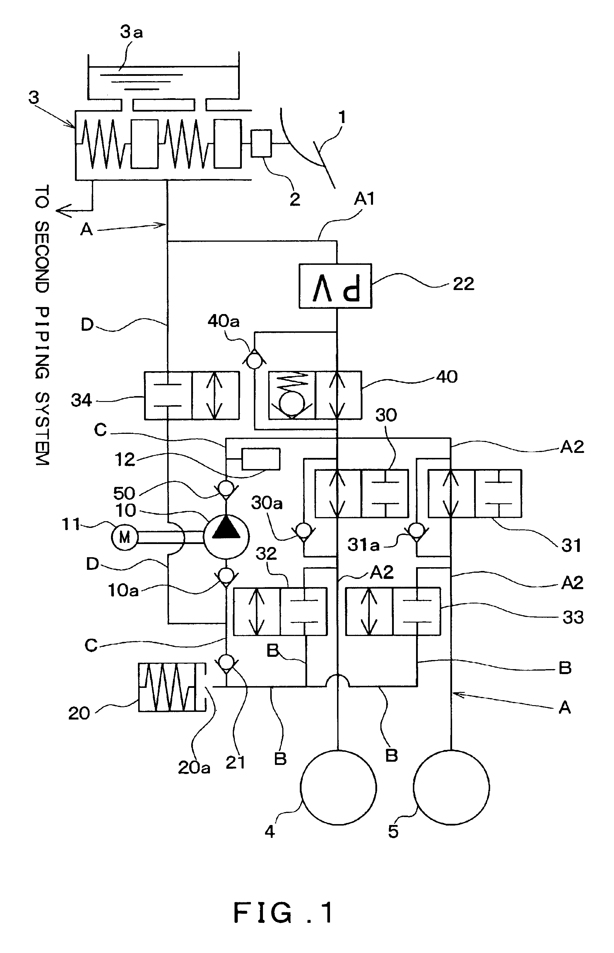
[0034]Hereinafter, a first embodiment will be explained with reference to the drawings. FIG. 1 is a schematic view of a brake piping system of a braking apparatus. A fundamental configuration of the braking apparatus will be explained with reference to FIG. 1. In the first embodiment, an example will be explained in which the braking apparatus according to the present invention is applied to a four-wheeled front-wheel-drive vehicle configured with a hydraulic circuit piping X that is provided with two piping systems, these being a front-right / rear-left wheel piping system and a front-left / rear-right wheel piping system, respectively.

[0035]As shown in FIG. 1, a brake pedal 1 is connected to a booster 2, and a brake depression force is increased by the booster 2. The booster 2 has a push rod that transmits the increased brake depression force to a master cylinder 3. A master cylinder pressure is generated by the push rod pushing a master piston disposed in the ...

second embodiment

[0067](Second Embodiment)

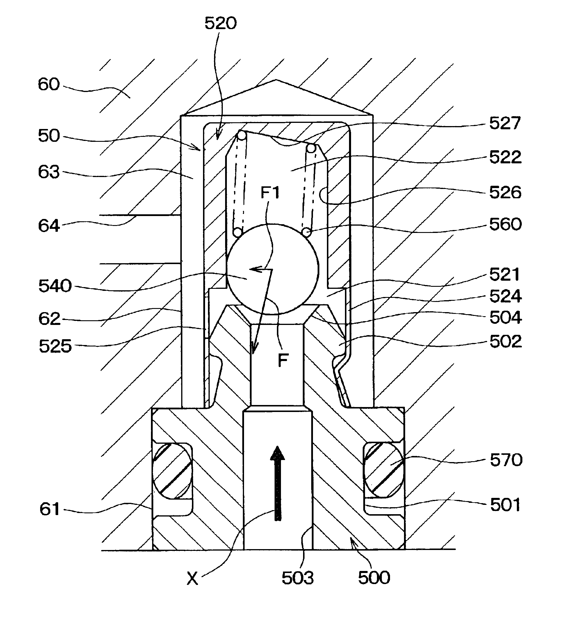
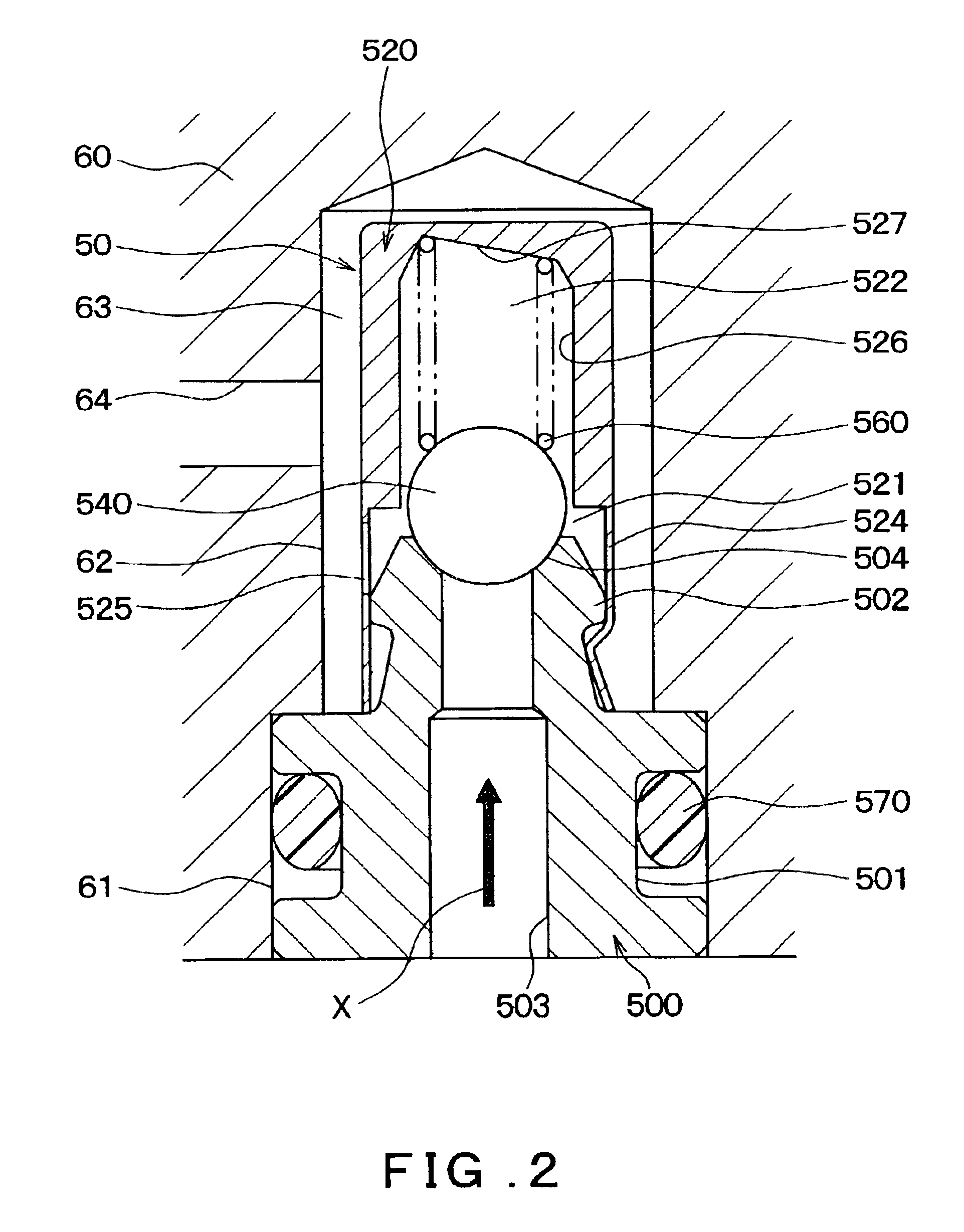
[0068]A check valve according to a second embodiment differs from that of the first embodiment with respect to the fact that the structure of the helical compression spring 560 is modified. Other structural elements are the same as those of the first embodiment.

[0069]As shown in FIG. 5, a helical compression spring 560A according to the second embodiment is a cylindrical helical compression spring. Two seat surfaces 561 and 562 of the helical compression spring 560A that are disposed at restrictive ends in an axial direction are parallel with each other in a non-compressed state. Further, the two seat surfaces 561 and 562 are not perpendicular to a central axis of the helical compression spring 560A.

[0070]By utilizing the characteristic that the two seat surfaces 561 and 562 are not perpendicular to the central axis of the helical compression spring 560A, the helical compression spring 560A is attached such that the obliqueness of the direction of the spring...

third embodiment

[0072](Third Embodiment)

[0073]A check valve according to a third embodiment differs from that of the first embodiment with respect to the fact that the structure of the helical compression spring 560. Other structural elements are the same as the first embodiment.

[0074]As shown in FIG. 6, a helical compression spring 560B is a cylindrical helical compression spring. Two seat surfaces 561 and 562 of the helical compression spring 560B that are disposed at restrictive ends in an axial direction are not parallel with each other when the helical compression spring 560B is in a non-compressed state. Further, the two seat surfaces 561 and 562 are not perpendicular to a central axis of the helical compression spring 560B.

[0075]By utilizing the characteristics that the two seat surfaces 561 and 562 are not parallel with each other and are not perpendicular to the central axis of the helical compression spring 560A, the helical compression spring 560B is attached such that the obliqueness of...


PUM


Abstract

In a check valve of the present invention, when a pressure action direction of a fluid on a valve body is assumed to be X, a spring receiving surface that abuts with a seat surface that is at one end in an axial direction of the helical compression spring is made to incline with respect to a surface perpendicular to the pressure action direction X. Accordingly, an urging force of the helical compression spring on the valve body acts obliquely with respect to the pressure action direction X. Thus the valve body is pressed to a side wall surface when the valve is opened, and vibration of the valve body is inhibited. Accordingly, it is possible to embody the invention with an extremely simple structure in which the spring receiving surface is inclined with respect to the surface perpendicular to the pressure action direction X.

Description

CROSS REFERENCE TO RELATED APPLICATION[0001]This application is based upon and claims the benefit of Japanese Patent Application No. 2002-176020 filed on Jun. 17, 2002, the content of which are incorporated herein by reference.[0002]1. Field of the Invention[0003]The present invention relates to a check valve that permits flow of fluid in only one direction. More particularly, it relates to a check valve that may be preferably disposed at a discharge side of a hydraulic pressure pump.[0004]2. Related Art of the Invention[0005]A conventional check valve for opening and closing a fluid path uses a ball that seats on and separates from a valve seat surface. In this type of the check valve, the ball, that acts as a valve body, is urged toward the valve seat surface (namely, in a valve closing direction) by a helical spring.[0006]When a pressure upstream of the valve seat surface becomes higher than a pressure downstream thereof by a predetermined pressure or more, the ball separates fro...

Claims


Application Information

Patent Timeline
IPC IPC(8): B60T8/34B60T8/48F04B53/10F16K15/04
CPCB60T8/4872B60T8/341Y10T137/7928
Inventor INAGE, SHOZONAGATANI, KANEYOSHIYANAI, KOJIYOSHIOKA, NOBUHIKO
Owner ADVICS CO LTD
Why Eureka
Try Eureka